Section 01 ENGINE MEASUREMENT
Subsection 01 (MEASUREMENT PROCEDURES)
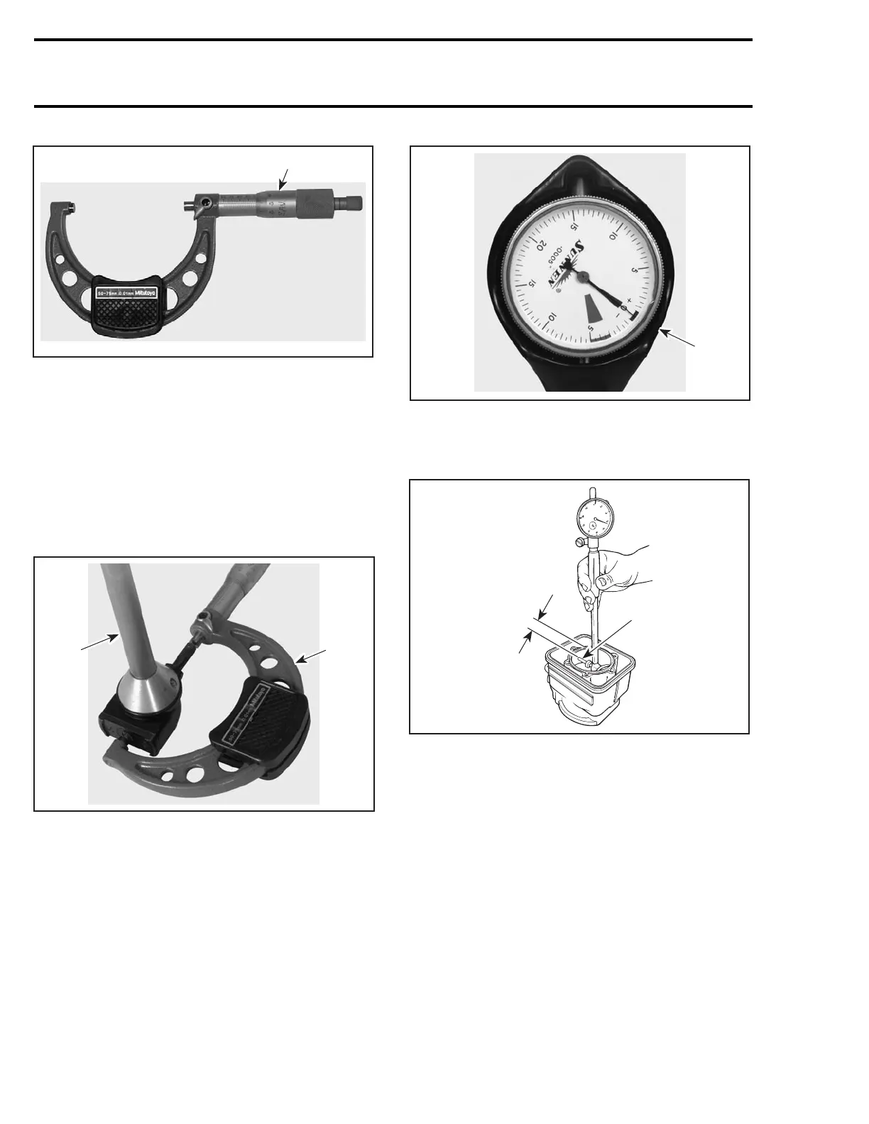
F00B08A
1
1. Micrometer set to the piston dimension
Proceed with FINAL MEASUREMENT PROCE-
DURE WITH EITHER A USED OR NEW PISTON
below.
Final Measurement Procedure with
either a Used or New Piston
With the micrometer set to the piston dimension,
adjust a cylinder bore gauge to the micrometer
dimension and set the indicator to zero.
F00B09A
1
2
1. Use the micrometer to set the cylinder bore gauge
2. Dial bore gauge
F00B0AA
1
1. Indicator set to zero
Position the dial bore gauge at 16 mm (5/8 in) be-
low cylinder top edge.
F01D0KA
1
A
1. Measuring perpendicularly (90°) to piston pin axis
A. 16 mm (5/8 in)
Read the measurement on the cylinder bore
gauge. The result is the exact piston/cylinder wall
clearance.
NOTE: Make sure the cylinder bore gauge indica-
tor is set exactly at the same position as with the
micrometer, otherwise the reading will be false.
RING/PISTON GROOVE
CLEARANCE
Using a feeler gauge, check clearance between
rectangular ring and groove. If clearance exceeds
specified tolerance, replace piston.
4 smr2005-085
 Loading...