Section02717ENGINE
Subsection 02 (MAGNETO SYSTEM)
DISASSEMBLY
NOTE: The magneto system can be disassembled
without removing the engine from the watercraft.
Magneto Cover
Remove screws no. 1 and wire support no. 2,
then withdraw magneto cover no. 3.
Magneto Flywheel and Ring Gear
To remove magneto flywheel no. 4,lockitwith
puller plate (P/N 420 876 081), sleeves (P/N 420
847 220) and extension handle (P/N 295 000 125).
Using three M8 x 35 screws (P/N 420 841 591), in-
stall screws through puller plate and slide sleeves
on screws then secure puller plate on magneto fly-
wheel so that sleeves are against ring gear no. 5.
F01D47A
2
3
4
1
1. Screw
2. Extension handle
3. Puller plate
4. Sleeve
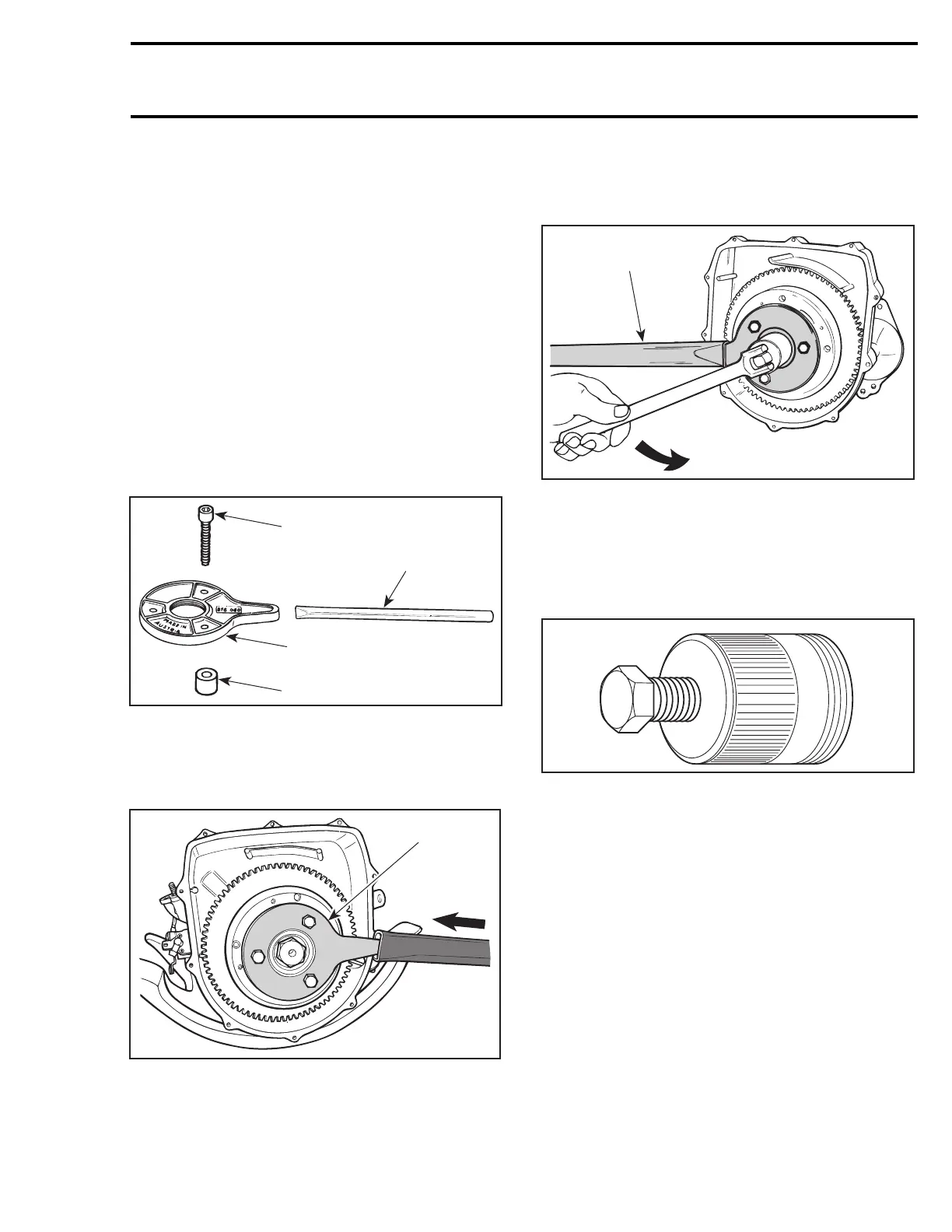
Install extension handle on end of puller plate.
F01D48A
1
TYPICAL
1. Sleeves on opposite side
Using a suitable socket, unscrew retaining nut
no. 6 COUNTERCLOCKWISE when facing it.
NOTE: If socket is found too large to be inserted in
puller plate, machine or grind its outside diameter
as necessary.
F01D4BA
1
TYPICAL
1. Extension handle locking crankshaft
Remove nut no. 6 and lock washer no. 7 from
magneto flywheel.
Magneto flywheel is easily freed from crankshaft
with magneto puller (P/N 529 035 547).
A00C1AA
Fully thread on puller in puller plate.
Tighten puller bolt and at the same time, tap on
bolt head using a hammer to release magneto fly-
wheel from its taper.
smr2005-076 19
 Loading...