Section02717ENGINE
Subsection 05 (ROTARY VALVE)
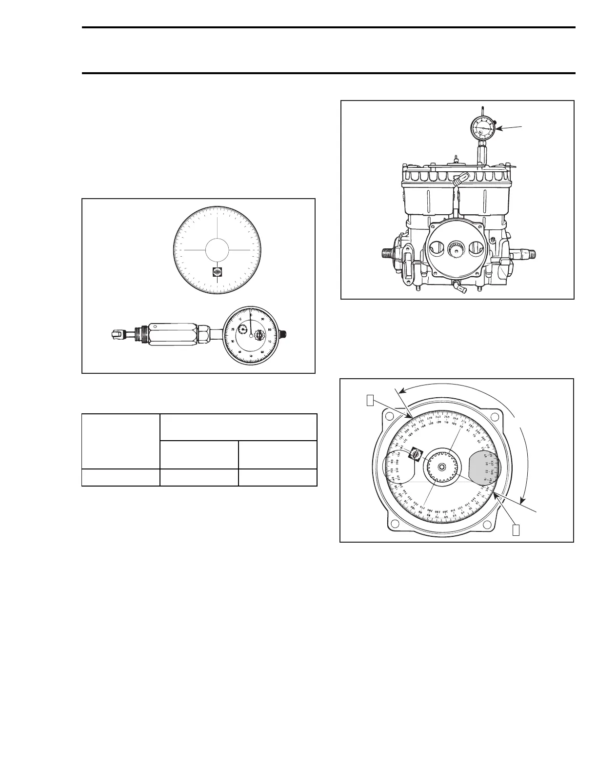
ROTARY VALVE TIMING
CAUTION: Never use the ridge molded in crank
case as a timing mark.
The degree wheel (P/N 529 035 607) and the TDC
gauge (P/N 295 000 143) are required to measure
rotary valve opening and closing angles in relation
with MAG side piston.
3
6
0
3
5
0
3
4
0
3
3
0
3
2
0
3
1
0
3
0
0
2
9
0
2
8
0
2
7
0
2
6
0
2
5
0
2
4
0
2
3
0
2
2
0
2
1
0
2
0
0
1
9
0
1
8
0
1
7
0
1
6
0
1
5
0
1
4
0
1
3
0
1
2
0
1
1
0
1
0
0
9
0
8
0
7
0
6
0
5
0
4
0
3
0
2
0
1
0
1
0
2
0
3
0
4
0
5
0
6
0
7
0
8
0
9
0
1
0
0
1
1
0
1
2
0
1
3
0
1
4
0
1
5
0
1
6
0
1
7
0
1
8
0
1
9
0
2
0
0
2
1
0
2
2
0
2
3
0
2
4
0
2
5
0
2
6
0
2
7
0
2
8
0
2
9
0
3
0
0
3
1
0
3
2
0
3
3
0
3
4
0
3
5
0
3
6
0
F00B0DB
529 035 607
295 000 143
Rotary valve must be set so that timing occurs as
follows:
TIMING
ENGINE
OPENING
BTDC
CLOSING
ATDC
717 147° ±5 65.5° ±5
Timing Procedure
The following timing procedure example uses
these specifications:
OPENING: 147° BTDC
CLOSING: 65° ATDC
Proceed as follows:
– Turning crankshaft, bring MAG side piston to
Top Dead Center using the TDC gauge.
1
F01D2IA
1. Bring piston to TDC
– For opening mark, first align 360° line of degree
wheel with BOTTOM of MAG side inlet port.
Then, find 147° line on inner scale of degree
wheel and mark crankcase at this point.
F01D3DC
147°
2
1
OPENING MARK
Step 1: Bottom of MAG inlet port. Align 360° line of degree wheel
Step 2: Find 147° on inner scale of degree wheel and mark here
NOTE: Do not rotate the crankshaft.
– For closing mark, first align 360° line of degree
wheel with TOP of MAG side inlet port. Then,
find 65° line on outer scale of degree wheel and
mark crankcase at this point.
smr2005-079 55
 Loading...