Section 01 ENGINE MEASUREMENT
Subsection 01 (MEASUREMENT PROCEDURES)
1
F01D4IA
3
2
4
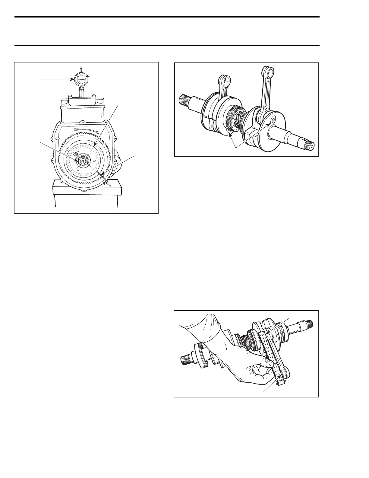
TYPICAL
1. TDC gauge
2. Degree wheel
3. Hand tighten nut
4. Needle pointer
– Remove TDC gauge and install on PTO side.
– Bring PTO piston at Top Dead Center.
Interval between cylinders must be exactly 180°
therefore, needle pointer must indicate 180° on
degree wheel (360° -180°=180°).
Any other reading indicates a misaligned crank-
shaft.
CrankshaftAlignmentatConnecting
Rod Journal
Counterweights can also be twisted on connect-
ing rod journal on any or both cylinder(s).
F01D1NB
1
1. Connecting rod journal alignment here
Such misalignment may make it difficult to manu-
ally turn the crankshaft. Verification can be done
by measuring deflection each end of crankshaft.
If deflection is found greater than specified toler-
ance, this indicates worn bearing(s), bent and/or
misaligned crankshaft. Proceed with the disas-
sembly of the engine.
CRANKSHAFT (DISASSEMBLED
ENGINE)
The following verifications can be performed with
theenginedisassembled.
Connecting Rod Straightness
Align a steel ruler on edge of small end connecting
rod bore. Check if ruler is perfectly aligned with
edge of big end.
F01D1QA
1
2
1. Ruler must be aligned with edge of connecting rod here
2. Align ruler here
6 smr2005-085
 Loading...