EB 2517 EN 29
Installation
5.3 Control line, compensation
chamber and needle valve
5.3.1 Control line
The control line must be provided at the site
of installation, e.g. a
3
/
8
“ pipe for steam or
an8x1or6x1mmpipeforair/water.
Connect the control line to the upstream line
(p
1
) at least one meter away from the valve
inlet.
Weld the control line at the side in the mid-
dle of the pipe, inclining at a ratio of ap-
proximately1:10uptothecompensation
chamber.
5.3.2 Control line kit
A control line kit for tapping pressure directly
at the valve body is available as an accesso-
ries part from SAMSON.
5.3.3 Compensation chamber
Î RefertoTable8
A compensation chamber (18) is required
forliquidsabove150°Caswellasfor
steam. The mounting position of the compen-
sation chamber is indicated by an adhesive
label on the chamber itself as well as by an
arrow and the word "top" stamped on the
top of the chamber.
Thismountingpositionmustbeadheredto;
otherwisethesafefunctioningoftheexcess
pressure valve cannot be guaranteed.
Weld the line coming from the pressure tap-
ping point to the
3
/
8
“ pipe socket on the
chamber. Install the compensation chamber
at the highest point of the pipeline. Conse-
quently, the control line between compensa-
tion chamber and actuator must also be in-
stalled with a downward slope. In this case,
use a
3
/
8
“pipewithscrewttings.
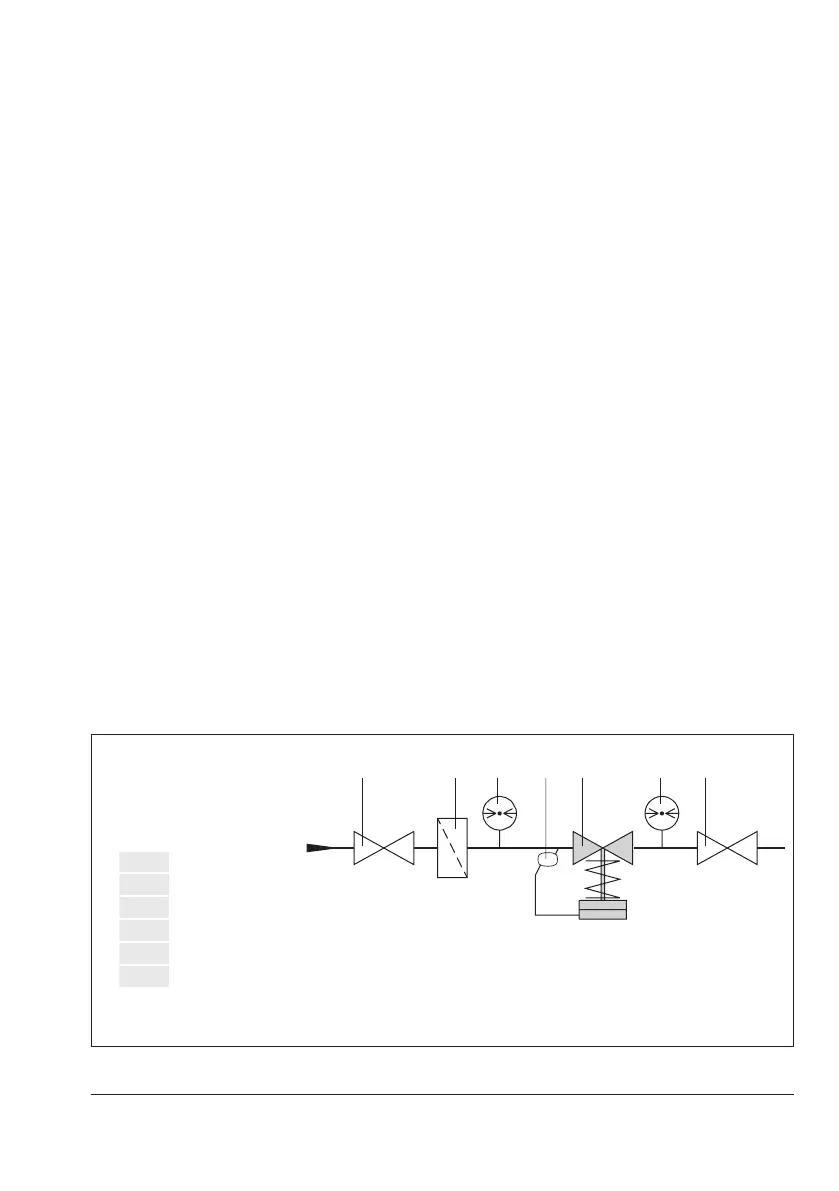
1 Shut-off valve
2 Strainer
3 Upstream pressure gauge
4 Excesspressurevalve
5 Downstream pressure gauge
18 Compensation chamber, e.g. for steam
Fig.7: Pressure control with Type41-73 (installation example)

 Loading...