EB 2517 EN 41
Servicing
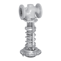
Mounting the set point springs
1. Place the set point springs (7) on the set
point adjuster (6).
2. Place the spring plate (7.1), nut (7.2)
andneedlebearingwithaxialdisk(7.4)
onto the spigot of the actuator bellows
(5.1).
3. DN15 to 50 without balancing bellows:
UseanAllenkey(4mm)toholdthebel-
lowsextensionstationaryandscrewon
the nut (7.2). Tighten the cap screw (7.3)
toxthenutinposition.Observethe
tighteningtorquesspeciedinsec-
tion7.5.
DN65 to 100 without balancing bel-
lows and DN15 to 100 with balancing
bellows:
Screwonnut(7.2)andxitinposition
with the cap screw (7.3). Observe the
tighteningtorquesspeciedinsec-
tion7.5.
4. Screw pillars (8.1) with the nuts (8.2) on-
to the valve and crossbeam (8). Observe
thetighteningtorquesspeciedinsec-
tion7.5.
5. Push the actuator onto the spigots of the
actuator bellows (5.1). Tighten the nuts
(9). Observe the tightening torques spec-
iedinsection7.5.
6. Install the regulator into the pipeline.
7. Screw on the control line (17). Observe
thetighteningtorquesspeciedinsec-
tion7.5.
8. Put the regulator into operation (see sec-
tion6.1).
Change the nameplate and conguration ID
after changing the set point range.
7.3 Replacing the seat and
plug
Risk of regulator damage due to excessively
high or low tightening torques.
Observe the specied torques on tightening
regulator components. Excessively tightened
torques lead to parts wearing out quicker.
Parts that are too loose may cause leakage.
Observe the specied tightening torques.
Make absolutely sure that no torque is
applied to the bellows seal (5.1) during
assembly or disassembly. Otherwise, the
metal bellows will be destroyed.
SAMSON's After-sales Service department
can support you concerning lubricant,
tightening torques and tools approved by
SAMSON.
To replace seat and plug, contact
SAMSON's After-sales Service department.
Further information is available in sec-
tion10.1.
Note
NOTICE
!
NOTICE
!
Note

 Loading...