36 EB 2517 EN
Start-up and operation
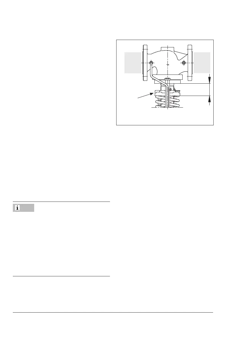
X
Set point adjuster
(6)
Fig.8: Set point adjustment with dimension x
6.3 Adjusting the set point
Î RefertoFig.3
Î The required upstream pressure is set by
turning the set point adjuster (6) using an
open-endwrench(uptoDN50with
widthacrossatsSW19andforDN65
andlargerwithSW24).Thesetpointof
the stainless steel regulator must be ad-
justed using the rod included.
Î Turn the set point screw clockwise () to
increase the pressure set point.
Î Turn the set point screw counterclockwise
() to reduce the pressure set point.
The pressure gauge located on the upstream
pressure side allows the adjusted set point to
be monitored.
An initial adjustment of the set point can also
be made by changing the spring tension and
Table7untilthedistancex(seeFig.8)is
reached.
Note during initial set point adjustment that
only a rough set point adjustment is per-
formed by turning the set point adjustment
until the distance x is reached. The special
properties of the process medium and plant
are not taken into account in this case.
Check the pressure at the pressure gauge
downstream of the regulator for a precise set
point adjustment.
Note

 Loading...