-20-
5
8
1
6
9
2
3
4
7
7
10
A
A
B
8
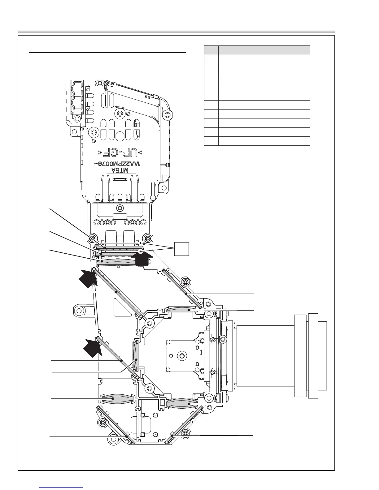
Fig.8
Optical Parts Disassembly
When mounting or assembling the optical parts in the opti-
cal unit, the parts must be mounted in the specified loca-
tion and direction as shown in figure below.
, Locations and Directions
No. Parts Name
1 Integrator lens (OUT)
2 Prism beam splitter (PBS)
3 Condenser lens (OUT)
4 Dichroic mirror (B)
5 Dichroic mirror (G)
6 Condenser lens (G)
7 Mirror (R)
8 Condenser lens (R)
9 Condenser lens (B)
10 Mirror (B)
5
8
1
6
9
2
3
4
7
7
10
A
A
B
8
Slit
The arrows in the figure indicate the mount direction
of the part for the replacement. Check the number
on the arrows and mount each part according to its
note;
A: The printed part no. comes to this side.
B: Rugged surface comes to this side.
 Loading...