-55-
Troubleshooting
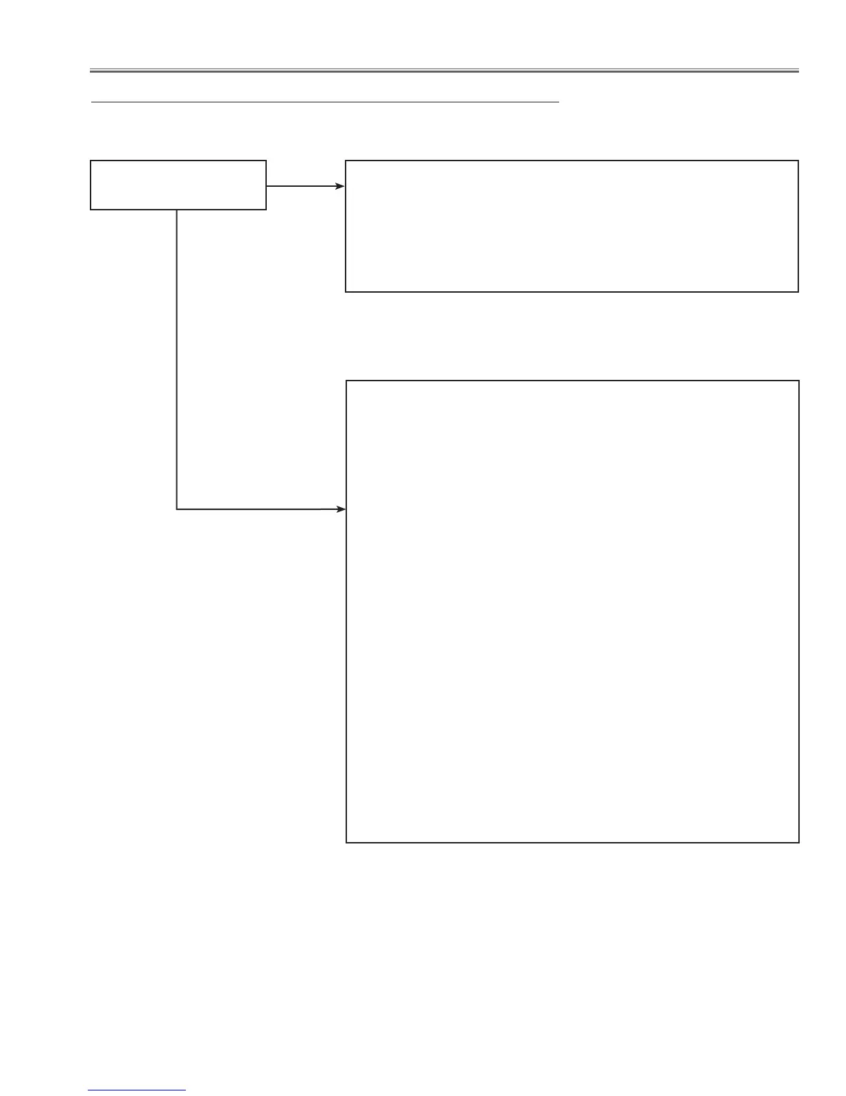
No Picture
No picture with all of in-
put sources
Check signal processing stage and LCD driving stage;
Check RGB S&H signals at test points TP_B1, TP_G1, TP_R1.
Check power supply circuit 15.5V and peripheral circuit.
Check ICs IC501, IC531, IC561, IC2501, IC2531, IC2561,
IC401, IC301 and peripheral circuits.
Yes
No
Check following steps.
Check each signal input stage;
Computer source
Check RGB signals on PC1.
R signal is applied to pin 82 of IC301<System Control>, G sig-
nal is applied to pin 260 and B signal is applied to pin 258 of IC
301.
HV sync signals are applied to pins 331 and 161 of IC301<System
Control> as the HS and VS signals.
Check RGB signals on PC2.
R2 signal is applied to pin 172 of IC301<System Control>, G2
signal is applied to pin 78 and B2 signal is applied to pin 256 of
IC 301.
HV sync signals are applied to pins 253 and 86 of IC301<System
Control> as the HS2 and VS2 signals.
S-Video source
Check S-video signal (Y/C).
S_CHROMA signal is applied to pin 265 of IC301<System Con-
trol>, and S_Y signal is applied on pin 264 of IC301.
Component video source
The component signals are applied to pins 82, 258, 409 of
IC301<System Control>.
Composite video source
Check composite video signal (Video).
The composite video signal is applied to pin 262 of IC301<System
Control>.
 Loading...