- 84 -
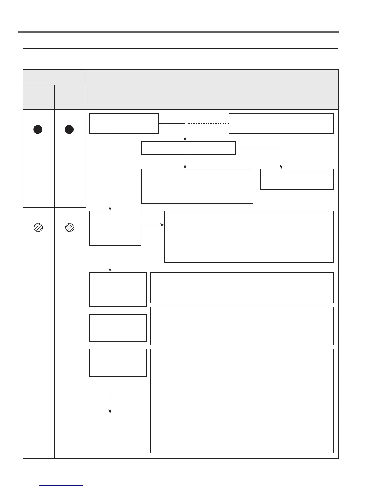
This projector provides a function which can be specified a defective area simply by indicating the LEDs on the control
panel. Connect the AC cord and turn the projector on and then check the LED indication.
● No Power
POWER (red) and
WARNING (red)
indicators are
lighting?
Yes
Check power supply lines, S5V, -5V, 17.5V, etc. on the Main board.
- Refer to the diagram "Power Supply Lines".
A n a b n o r m a l i t y
occurs on the sec-
ondary power sup-
ply lines
Power failure detection diodes detect the fan operation stop.
Check FN901/902/903/904/905 and peripheral circuit.
Check connectors K8E/K8F from TH901/TH902.
- Refer to the diagram "Fan control circuit".
A n a b n o r m a l i t y
occurs on the fan
control circuits.
Check power starter signals as follows:
- STANDBY_SW signal (Power-on:H) is output from pin 9 of IC4801 and
sent to the Power Board and 17.5V, S16V_F, 6.5V, S5V, -5V lines are sup-
plied.
- POWER_ON_SW signal (Power-on:H) is output from pin 25 of IC301 and
sent to the Power Board and lamp ballast 375V line is supplied.
- 3.3V_SW signal (Power-on:H) is output from pin 346 of IC301 and sent to
IC7601, 7651, 7611 then 3.3V, 2.5V, 1.0V lines are supplied.
- 1.8V_SW signal (Power-on:H) is output from pin 247 of IC301 and sent to
IC7641, then 3.3V lines are supplied.
- 15V_SW signal (Power-on:H) is output from pin 140 of IC301 and sent to
IC7631, then 9V line is supplied.
- FAN_SW signal (Power-on:H) is output from pin 437 of IC301 and applied
to the Fan power supply circuit.
A n a b n o r m a l i t y
occurs on powe r
starter signals.
Check following
items
The symptom indicates that the projector detected an abnor-
mality in the cooling fan operation or in the power supply sec-
ondary circuits. Check fan operation and power supply lines,
and the driving signal status.
- POWER_FAIL (Error:L) signals are sent to IC301, then IC301 shuts
down the power supply circuit.
Does a indicator flash or
light?
The primary power supply circuit does
not operate properly.
Check Varistor (VA611).
Check Power Board.
Is fuse (F601) broken?
Check SS3.3V power supply line.
- When the main power switch is ON,
SS3.3V line is supplied to IC4801(Sub CPU).
To next page
POWER
red/green
Indicators
WARNING
red
Yes
No
Yes
No
Troubleshooting
Troubleshooting
 Loading...