21
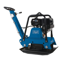
Working position Fig. 2.4
In the working position, the entire trolley section is folded
up and latched into the hooks on the lower handle frame.
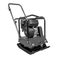
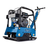
Transport Fig. 2.5
For transport purposes, the upper handle frame is folded
in, the trolley section is released from the hooks on the
lower handle frame and swung under the machine by lift-
ing it. The plate vibrator can now be moved.
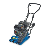
Assembling the rubber mat Fig. 2.6
Fixing parts:
3 hexagon bolts M 10 x 30
3 spring washers A 10 mm dia.
For mounting the rubber mat, the machine with the rub-
ber plate has to be placed onto the rubber mat.
Fasten the rubber mat on both sides using 3 hexagon
bolts M 10 x 30 and 3 washers 10 mm dia. each. Firmly
tighten all bolts.
Attention:
Only use the rubber mat for vibrating concrete stones,
concrete plates and similar materials. For vibrating
gravel, stone chips and similar materials, the rubber mat
must be removed.
3R]\FMDURERF]D5\V
: SR]\FML URERF]HM QDVWĊSXMH XQLHVLHQLH FDáHJR SRGZR]LD
L ]DKDF]HQLH JR ]D SRPRFą ]DSDGHN QD KDNDFK GROQHJR
XFKZ\WX
7UDQVSRUW5\V
'R FHOyZ WUDQVSRUWRZ\FK JyUQ\ XFKZ\W ]RVWDMH UR]áRĪRQ\
SRGZR]LH]RVWDMH]ZROQLRQH]KDNyZQDGROQ\PXFKZ\FLHL
SRSU]H]XQLHVLHQLH]RVWDMHZVXQLĊWHSRGPDV]\QĊ
7HUD]PRĪQDSRUXV]DüZLEUDWRUHPSá\WRZ\P
0RFRZDQLHPDW\JXPRZHM5\V
&]ĊĞFLPRFXMąFH
ĞUXEV]HĞFLRNąWQ\FK0[
SRGNáDGHNRĞUHGQ$PP
:FHOX]DPRQWRZDQLDPDW\JXPRZHMPDV]\QD]Sá\WąJX-
PRZąZLQQDE\üXPLHV]F]RQDQDPDFLHJXPRZHM
3U]\PRFRZDüPDWĊJXPRZą]REXVWURQXĪ\ZDMąFĞUXE
KHNVDJRQDOQ\FK0[LSRGNáDGHNPP]NDĪGHM
VWURQ\0RFQRGRNUĊFLüZV]\VWNLHĞUXE\
8ZDJD
0DW\ JXPRZHM XĪ\ZDü Z\áąF]QLH SU]\ REUyEFH Sá\W L SR-
ZLHU]FKQLEHWRQRZ\FKOXESRGREQ\FKPDWHULDáRZ3U]\XELMD-
QLXĪZLUXOXEWHPXSRGREQ\FKPDWĊJXPRZąQDOHĪ\]GMąü
 Loading...