Connecting
Tightening torques
Cable glands
NOTICE
Take care not to damage the cable jacket.
T htening torig ques must be adapted to suit the type of cable jacket material in use.
You should refer to the table in order to find the correct tightening torque for any
d plastic cable glands that are to be mountemetal an
w
d directly on the machine, as
ell as for any other screw-type connections (such as adapters).
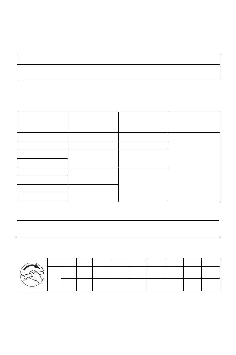
Table 1 Tightening torques for cable glands
Metal
± 10%
Nm
Plastic
± 10%
Nm
O ring
String ∅
mm
M 12 x 1,5 8 1,5
M 16 x 1,5 10 2
M 20 x 1,5
M 25 x 1,5
12 4
M 32 x 1,5
M 40 x 1,5
18
M 50 x 1,5
M 63 x 1,5
20
6
2
Terminal boxes, end shields, grounding conductors, sheet metal fan
covers
Note
The specified tightening torques are applicable unless other values are indicated.
Table 2 Tightening torques for screws on the terminal box, end shields, screw-type
grounding conductor connections
Thread ∅ M 4 M 5 M 6 M 8 M 10 M 12 M 16 M20
min 2 3.5 6 16 28 46 110 225
Nm
max 3 5 9 24 42 70 165 340
Standard machines_Operating_Instructions_Compact
10 56100000002001 EN, 01/2010
 Loading...


