EasyManuals Logo

Siemens S7-1200 User Manual

Siemens S7-1200
132 pages
To Next Page IconTo Next Page
To Previous Page IconTo Previous Page
Page #28 background imageLoading...
Page #28 background image
LEDs and connectors
2.2 LEDs
CP 1243-7 LTE
28 Operating Instructions, 01/2015, C79000-G8976-C381-01
2.2
LEDs
LEDs of the module
The CP has the following LEDs for displaying the status:
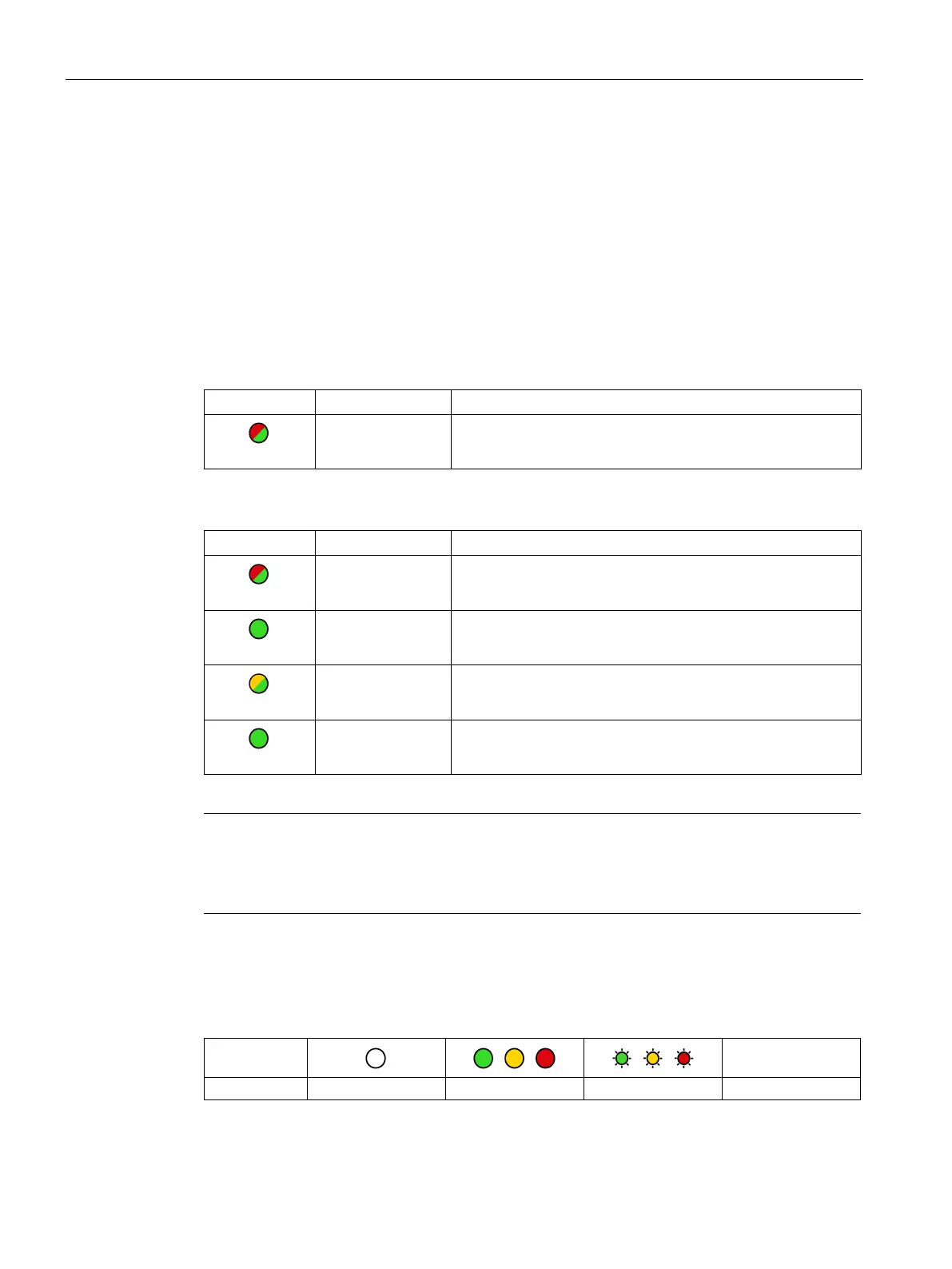
"DIAG" LED on the front panel
The "DIAG" LED that is always visible shows the basic statuses of the module.
LEDs below the upper cover of the housing
These LEDs provide further details on the module status.
Table 2- 1 LED on the front panel
LED / colors
Name
Meaning
red/green
DIAG
Basic status of the module
Table 2- 2 LEDs below the upper cover of the housing
LED / colors
Name
Meaning
red/green
NETWORK Status of the connection to the mobile wireless network
green
CONNECT
Status of the connection to the master station
yellow / green
SIGNAL QUALITY
Signal quality of the mobile wireless network
green
VPN
Status of the VPN connection
Note
LED colors when the module starts up
When the module starts up, all its LEDs
are lit for a short time. Multicolored LEDs display a
color mixture. At this point in time, the color of the LEDs is not clear.
Display of the operating and communication status
The LED symbols in the following tables have the following significance:
Table 2- 3 Meaning of the LED symbols
Symbol
-
LED status
OFF
ON (steady light)
Flashing
Not relevant
The LEDs indicate the operating and communications status of the module according to the
following scheme:

Table of Contents

Other manuals for Siemens S7-1200

Questions and Answers:

Question and Answer IconNeed help?

Do you have a question about the Siemens S7-1200 and is the answer not in the manual?

Siemens S7-1200 Specifications

General IconGeneral
Digital InputsIntegrated in CPU or via signal modules (SM)
Digital OutputsIntegrated in CPU or via signal modules (SM)
Analog InputsIntegrated in CPU or via signal modules (SM)
Analog OutputsIntegrated in CPU or via signal modules (SM)
CommunicationPROFINET
Communication Ports1 x PROFINET
I/O ModulesSignal Modules (SM)
ProgrammingSTEP 7
Power Supply24V DC
Operating Temperature0°C to 55°C
Expansion ModulesCommunication Modules (CM), Battery Modules (BM)

Related product manuals