Start-Up 09.02
4-2 Siemens AG 6SE7087-6AK85-1AA0
Rectifier/Regenerating Unit Operating Instructions
♦ Closed-loop control variant:
a) Parallel connection (see Section 3.7)
The output current can be increased by connecting up to 2 "parallel units of identical rated
current in parallel
with the power section of a rectifier/regenerating unit of size K ("basic
unit"). The "basic unit" controls the DC-link voltage. The firing pulses of the basis unit are
transmitted to the parallel unit(s) via ribbon cable. A parallel unit does not
contain a CUR
electronic module.
When connected in parallel, the load current must be reduced by 10 % with respect to the
total rated current.
Due to the use of identical power sections, commutating reactors, autotransformers as well
as identical cable lengths for connection to the mains supply, an almost symmetrical division
of current between the "basic unit" and the "parallel unit(s)" can be ensured.
b) 12-pulse mode (see Section 3.8)
Two rectifier/regenerating units are connected in parallel on the output side
and fed on the
line side with galvanically isolated AC supplies, each displaced by 30 degrees. A
rectifier/regenerating unit controls the DC-link voltage and supplies a second
rectifier/regenerating unit with the current setpoint. The second rectifier/regenerating unit
that is linked to the first via the SST2 serial interface (RS485 interface option) with peer-to-
peer protocol only becomes a "12-pulse slave" after parameterization.
12-pulse mode is used to reduce the harmonic loading on the system and to increase the
performance for high-power rectifier/regenerating units.
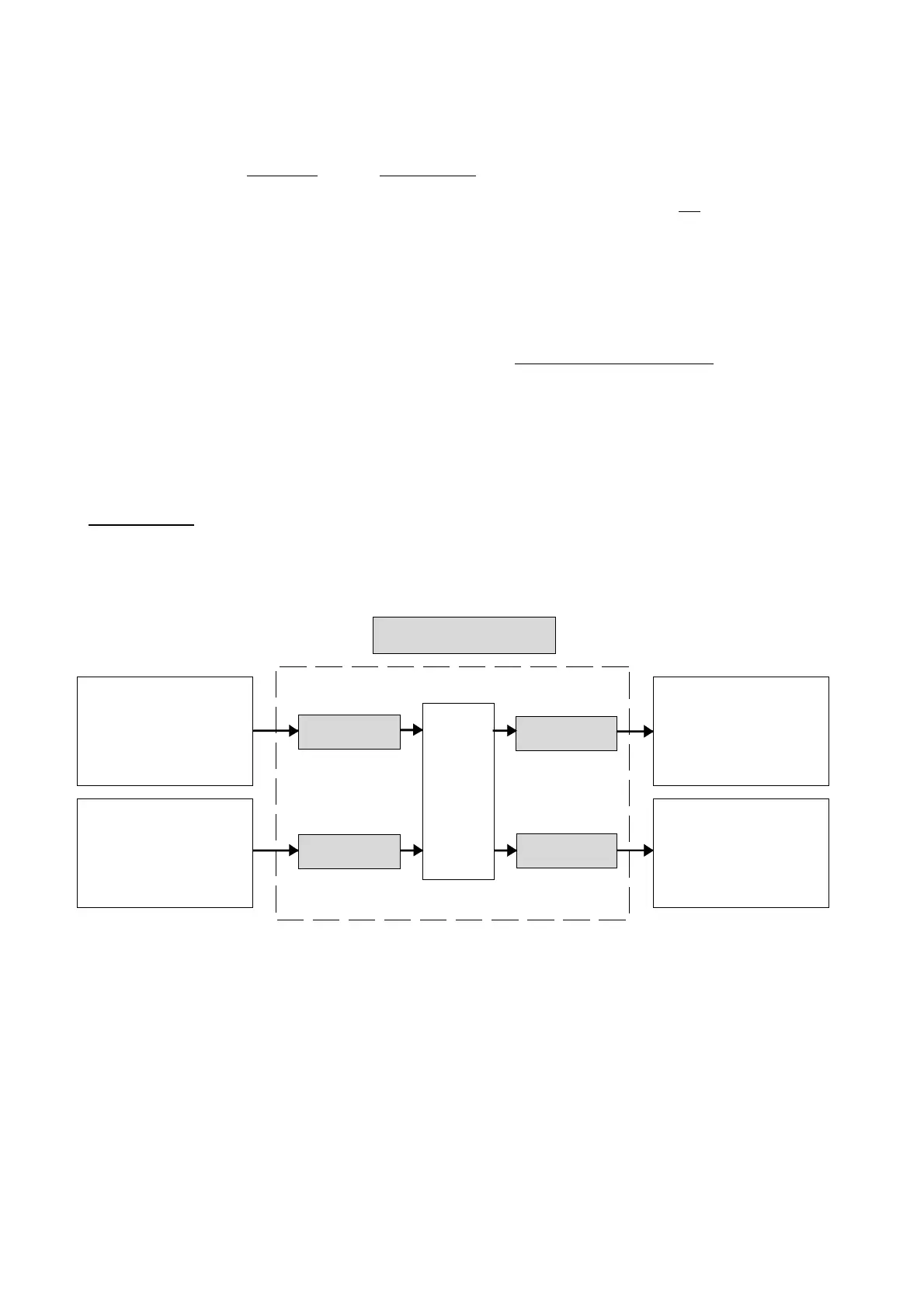
"Process data":
♦ "Process data" are commands and setpoints from "outside" fed into the rectifier/regenerating
unit, as well as signals and actual values which are output from the rectifier/regenerating unit
Setpoint
chanal
Op./cl-loop
control
Commands
"Control Word"
Setpoints
Messages
"status word"
Actual values
Rectifier/regenerating unit
Process data
e.g.: "ON command"
Only: Id setpoint in
12-pulse operation
e.g.: "fault
e.g. output current
- Binary inputs BE
(terminals)
- Parameterizing unit (PMU)
- Operator control panel (OP)
- Serial interfaces
(SST1, SST2, SCB, CB, TB)
Sources
Destinations
- Serial interfaces
(SST1, SST2, SCB, CB, TB)
- Binary outputs BA
(terminals)
- Parameterizing unit (PMU)
- Operator control panel (OP)
- Serial interfaces
(SST1, SST2, SCB, CB, TB)
- Analog outputs AA
(terminals)
- Parameterizing unit (PMU)
- Operator control panel (OP)
- Serial interfaces
(SST1, SST2, SCB, CB, TB)
AoteWell Automation Sales Team
Buy Siemens PLC HMI Drives at AoteWell.com
 Loading...


