TC35i: Migration from TC35 to TC35i
PRELIMINARY
TC35_TC35i_MIG_01_V01.01 29.1.2003 Page 12 of 34
4.4 Power Supply
4.4.1 General
TC35 and TC35i need to connect the power supply to the ZIF connector (5 pins each V
BATT+
and GND). Power supply has to be a single voltage source at BATT+.
Power Supply ASIC handles all the key functions for supplying power.
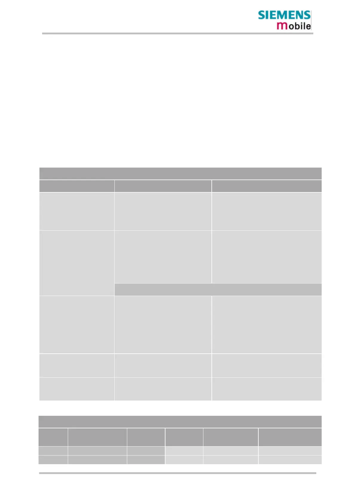
The following tables show an overview of main power supply points with TC35 and TC35i
Table 4-3: Power supply signals
General
Feature TC35 TC35i
Input voltage range:
Five pins of BATT+ and GND must be
switched in parallel for supply purposes
because peaks of up to 2A may occur.
V
I
= 3.3V to 5.5V
V
I,typ
= 4.2V
I
nom
˜ 2A, in burst
Five pins of BATT+ and GND must be switched
in parallel for supply purposes because peaks of
up to 3A may occur.
V
I
= 3.3V to 4.8V
V
I,typ
= 4.2V
I
nom
˜ 2A, in burst
V
out
= 2.3V
R
out
≈ 220k.
V
low,max
= 0.45V @ Iout = 10µA
t
low
≈ 100ms
Signal: falling edge and hold for t
low
Open drain/collector driver is required to
pull down this pin to power on the GSM
Engine.
R
I
˜ 100kΩ, C
I
˜ 1nF
V
ILmax
= 0.5V @ I
max
= 20µA
V
Openmax
= 2.3V
t
low
≈ 100ms
Signal: falling edge and hold for t
low
Ignition:
ON
~~~
|____|
~~~
Active Low ≥ 100ms
Emergency shutdown:
(Watchdog)
Via /PD (pin no. 31)
This line must be driven by an Open Drain
or Open Collector driver.
Emergency shutdown deactivates the
modules power supply.
Signal
~~~
|______|
~~~
Active Low ≥
3.5s
via EMERGOFF (pin no. 31)
This line must be driven by an Open Drain or
Open Collector driver.
Emergency shutdown deactivates the modules
power supply.
Signal
~~~
|______|
~~~
Active Low ≥ 3.2s
Synchronization:
Indication of increased current
consumption during uplink
transmission burst
V
out,low,max
= 0.2V @ I= 0.1mA
V
out,high,min
= 2.25V @ I=-0.1mA
V
out,high,max
= 2.76V
V
OLmax
= 0.3V @ I = 0.1mA
V
OHmin
= 2.25V @ I = -0.1mA
V
OHmax
= 2.73V
Power saving: Supported trough AT+CFUN
Functionality levels <fun>=0
Supported trough AT+CFUN
Functionality levels <fun>=0, 5 , 6, 7 and
8
Table 4-4: Power consumption comparison
Power consumption
Device Stand-by Sleep Idle Talk mode at
EGSM900/1800
Talk mode (peak) at
EGSM900/1800
TC35 50µA typ 3mA typ 10mA typ 300mA/270mA 1.8A typ
TC35i 50µA typ 3mA typ 25mA 300-400mA 2A typ
 Loading...