TC35i: Migration from TC35 to TC35i
PRELIMINARY
TC35_TC35i_MIG_01_V01.01 29.1.2003 Page 19 of 34
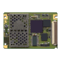
4.10 Mounting and installation
Appropriate installation and mounting to the host housing / enclosure is essential for reliable
operation of the GSM engine.
TC35i & TC35
The TC35 board provides three mounting holes. To properly mount it to the host device you
can use M1.6 or M1.8 screws plus suitable washers. The maximum diameter of the screw
head, including the washer, must not exceed 4 mm.
To prevent mechanical damage, be careful not to force, bend or twist the GSM engine. Make
sure it is positioned flat against the host device.
Avoid placing the TC35 board tightly to the host device. Instead, it is recommended
to set the spacers between the module and the host device. If your design approach does not
allow for spacers make sure the host device provides an opening for the RF part.
Avoid exerting any pressure on the shielding covers. Contact springs or other components
must not be fastened to the covers. In extreme conditions, you run the risk of short-circuit if
the cover was damaged or distorted due to pressure. Furthermore, the covers must not be
used to apply any solder joints.
For snap-in concept please be aware that the TC35i PCB is thinner then the TC35
PCB
 Loading...