EasyManuals Logo
Home>Simplicity>Lawn Mower>LEGACY Series

Simplicity LEGACY Series User Manual

Simplicity LEGACY Series
312 pages
To Next Page IconTo Next Page
To Previous Page IconTo Previous Page
Page #107 background imageLoading...
Page #107 background image
7 - 39
7 Electrical System Service
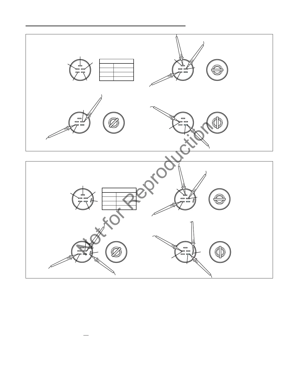
Component Tests
TEST OFF POSITION
1. Set VOM to Ohm.
2. Turn the ignition key switch to the OFF position.
3. Connect test leads to G and M. The test meter should
show continuity (zero ohm if using an ohm meter).
4. Turn the ignition key switch to the RUN position. The
test meter should show no
continuity (infinity/open if
using an ohm meter).
S
L
OFF
RUN
START
START
ON
OFF
TERMINALS
B
B
L
OFF
RUN
START
G
M
OFF
RUN
START
L
S
B
IGNITION SWITCH
POSITION
1. OFF
2. RUN
3. START
CIRCUIT MAKE
G & M
B & L
B & L & S
M
G
Figure 40. Ignition Switch Tests 5-Pin Steel Body (Early Models)
5. Repeat steps 2 through 4 for each combination of ter-
minals listed in the table for the OFF circuit of the
appropriate figure (Figure 40 for 5-pin steel body
switches and Figure 41 for the 6-pin steel body
switches).
6. Check all other connection combinations for no conti-
nuity (open). The combinations tested in steps 2
through 4 should be the only combinations that have
continuity; all other connection combinations should
have no continuity.
START
ON
OFF
TERMINALS
B
M
L
S
B
IGNITION SWITCH
POSITION
1. OFF
2. RUN
3. START
CIRCUIT MAKE
G & M & A
B & L & A
B & L & S
M
G
A
S
L
OFF
RUN
START
B
L
OFF
RUN
START
A
G
OFF
RUN
START
A
Figure 41. Ignition Switch Tests 6-Pin Steel Body (Later Models)
Not for Reproduction

Table of Contents

Questions and Answers:

Question and Answer IconNeed help?

Do you have a question about the Simplicity LEGACY Series and is the answer not in the manual?

Simplicity LEGACY Series Specifications

General IconGeneral
BrandSimplicity
ModelLEGACY Series
CategoryLawn Mower
LanguageEnglish

Related product manuals