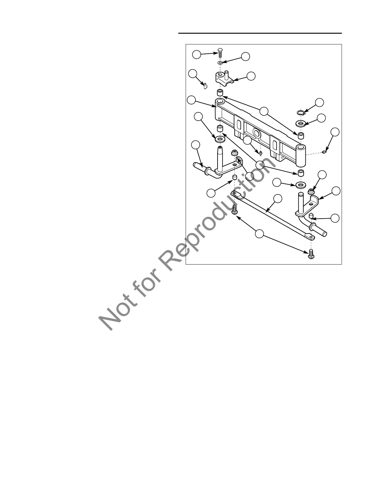
Figure 13. Removing Front Spindles
A. Key I. Spacer
B. Steering Hub Assembly J. Tie Rod
C. Bushing K. Capscrews
D. Retaining Ring L. Right Spindle
E. Washer M. Axle
F. Grease Fitting N. Capscrew
G. Hex Nut O. Washer
H. Left Spindle
8 Power Steering Service
Front Spindle Removal and Installation
8 - 10
Front Spindles – Removal
1. Park the tractor on a level surface.
2. Place blocks in front of and behind the rear wheels.
3. Turn the ignition key switch to the OFF position,
remove the key, set the parking brake, and turn the
PTO switch off.
4. Disconnect the negative (-) battery cable
(see Section 7, ELECTRICAL SYSTEM SERVICE).
5. Disconnect spark plug wires to prevent the possibility
of accidental starting.
6. Hoist the front end of tractor and securely support the
front end using the proper jack stands so that work
can be safely performed underneath the tractor.
7. Remove both front wheels (see Section 3, MAINTE-
NANCE).
8. Remove steering cylinder (see Steering Cylinder
Removal, in this section).
9. Remove the capscrews (K, Figure 13) and hex nuts
(G) that secures the tie rod (J) to the spindles (H and
L). Remove the tie rod (J) and spacers (I).
10. Remove steering hub assembly (B) and key (A) from
the right spindle (L).
11. Slide the right spindle (L) out of the axle (M).
12. Remove the retaining ring (D) and washer (E) from
the left spindle (H).
13. Slide the left spindle (H) out of the axle (M).
14. Remove the bushings (C) from the axle (M) and
inspect the bushings for wear, cracks, or damage.
Replace if necessary.
I
J
G
E
E
D
B
A
C
C
E
I
H
G
L
K
M
F
F
Front Spindles – Installation
1. Clean the front spindle area of the axle (M, Figure 13).
2. Replace the bushings (C) in the axle (M).
3. Clean spindles and apply thin film of grease to wheel
and axle bearing areas.
4. Slide the left spindle (H) into the axle (M).
5. Install the retaining ring (D) and washer (E) onto the
left spindle (H).
6. Slide the right spindle (L) into the axle (M).
7. Install steering hub assembly (B) and key (A) onto
the right spindle (L). Secure with a washer and cap-
screw. Torque to 55 ft.lbs.
8. Install the tie rod (J) and spacers (I). Replace the
capscrews (K) and hex nuts (G) to secure the tie rod
(J) to the spindles (H and L). Torque hex nuts (G) to
40-50 ft.lbs.
9. Remove both front wheels (see Section 3, MAINTE-
NANCE).
10. Install steering cylinder (see Steering Cylinder
Installation, in this section).
11. Remove the tractor from the hoist.
12. Reconnect spark plug wires.
13. Reconnect the negative (-) battery cable
(see Section 7, ELECTRICAL SYSTEM SERVICE).
14. Start engine and check for leaks.
15. Turn wheels from lock to lock several times.
16. Shut off engine and check for proper fluid level. Fill to
proper level.
O
N

 Loading...