7 - 15
7 Electrical System Service
Linear Circuit Diagrams
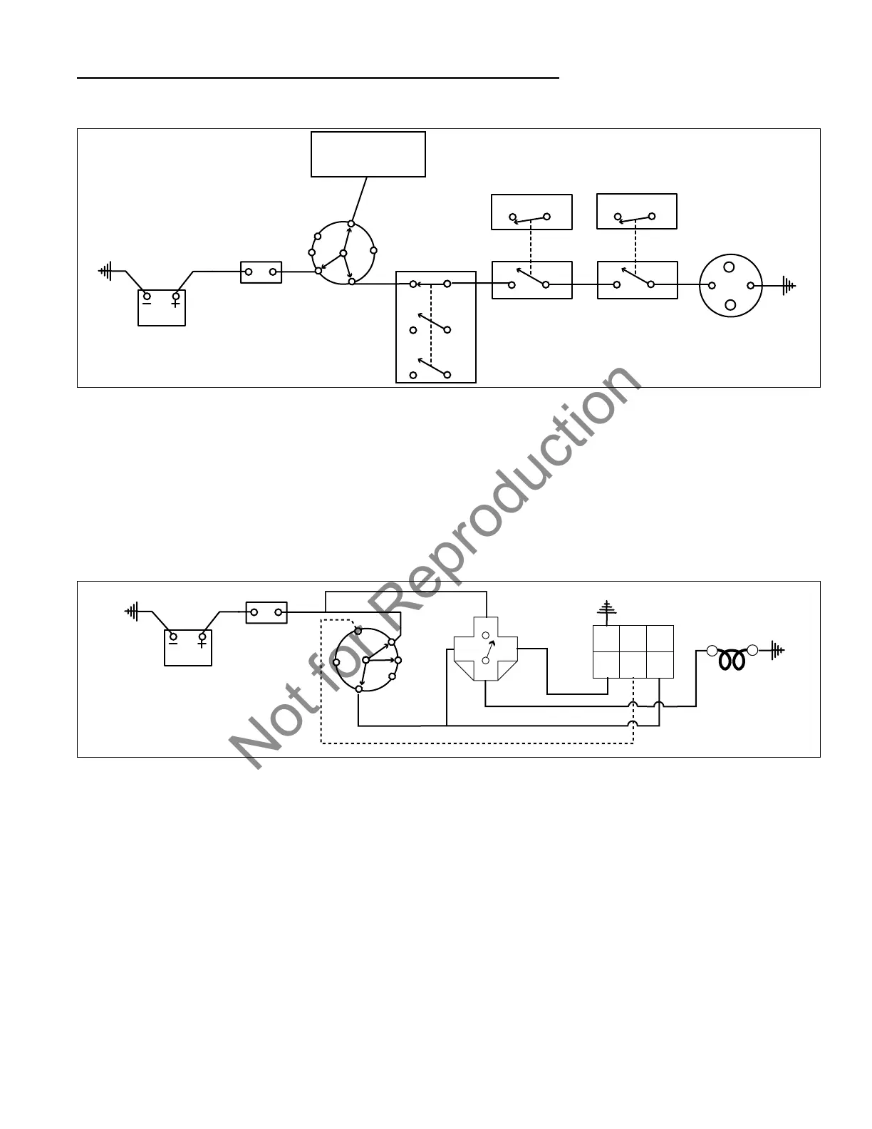
CRANKING CIRCUIT
See Figure 8.
The cranking circuit is only active when the ignition key
switch is in the start position.
Power is supplied through the circuit breaker to the B ter-
minal of the ignition switch. When the switch is turned to
the start position, contacts are closed between the B - L
terminals and B - S terminals of the ignition switch.
Figure 8. Typical Cranking Linear Circuit Diagram (All Models)
The B - S connection applies power to the starter sole-
noid. This circuit contains safety interlock components
that will prevent the tractor from starting if all interlocks
are not met.
The B - L connection applies power to the ignition sys-
tem and other electrical components.
PREHEAT CIRCUIT
See Figure 9.
The preheat circuit is only active when the ignition key
switch is first placed in the “RUN” (ON) or “START” posi-
tion. The purpose is to supply current to the glow plug
for a timed duration before the engine is started. This
allows the glow plugs to heat up to a point that will ignite
the compressed fuel.
Power is supplied through the circuit breaker to the B ter-
minal of the ignition switch. When the switch is turned to
the “ON” position, contacts are closed between the B - L
terminals of the ignition switch.
The B - L connection applies power to terminal 85 of the
glow plug relay and terminal A of the preheat timer. At
the time when terminal A of the preheat timer is ener-
gized, a contact in the preheat timer is closed, connect-
ing terminals C and D. This provides a path to ground
for terminal 86 of the glow plug relay through the preheat
timer, which energizes the glow plug relay. This closes
the contact between terminals 87 and 30, which allows
the glow plug to heat up.
The preheat timer will keep the glow plug relay energized
for a duration of time as specified by the timer, the igni-
tion key switch is turned off, or when terminal B is ener-
gized by turning the ignition key to the “START” position.

 Loading...