7 - 16
7 Electrical System Service
Linear Circuit Diagrams
IGNITION SHUTDOWN CIRCUIT
See Figures 12 and 13.
Ignition shutdown occurs when the ignition key switch is
turned to the “OFF” position or the safety system kills the
engine.
When the ignition shutdown occurs, the engine is
stopped by the following:
Air-Cooled Models – the magneto is grounded through
the ignition key switch (Figure 12).
Diesel Models – power is removed from the fuel injection
pump (Figure 13).
Liquid-Cooled Models – power is removed from the igni-
tion coil (Figure 13).
PTO CLUTCH CIRCUIT
See Figure 11.
The PTO clutch circuit becomes active only when the
PTO clutch is engaged, which occurs when the PTO
clutch switch is engaged (pulled up). Power to the PTO
clutch circuit comes from the ignition key switch when it
is in the “RUN” (ON) position.
When either PTO clutch switch is depressed the clutch is
energized, causing the clutch to engage and drive the
attachment connected to the tractor. When the PTO
clutch is engaged, the same power that is energizing the
clutch is connected to the PTO clutch indicator lamp on
the instrument panel.
NOTE: When there is not a rear PTO clutch installed,
jumpers will need to be installed on the connector for the
rear PTO clutch switch.
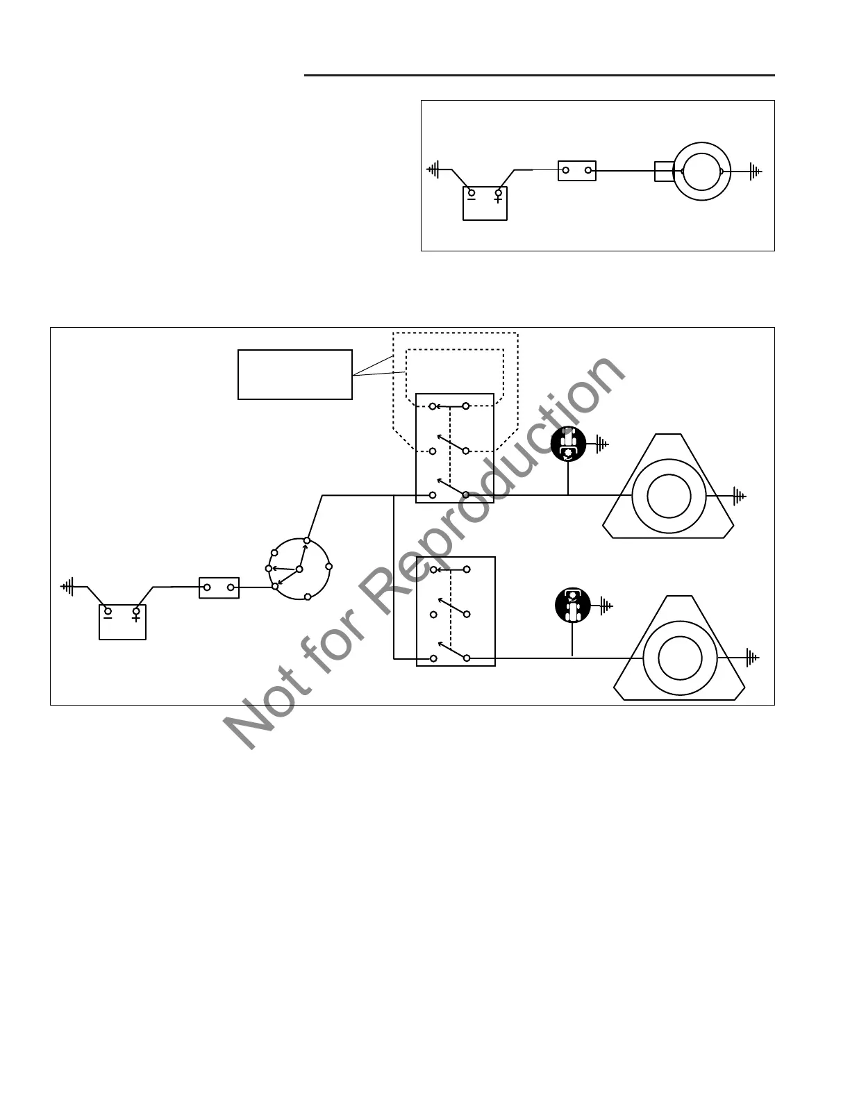
Figure 11. Typical PTO Clutch Linear Circuit Diagram (All Models)
CHARGING CIRCUIT
See Figure 10.
The charging circuit is always active, regardless of the
position of the ignition switch. The charging circuit is
controlled and protected by the voltage regulator which is
housed in the alternator. The voltage regulator protects
the tractors electrical system by regulating the power
output of the alternator, preventing excessive current
draw and reverse power feed.
The alternator charges and equalizes the battery after
each start and supplies the tractors electrical devices
with power during operation.

 Loading...