16 - 11
16 PTO Clutch Service
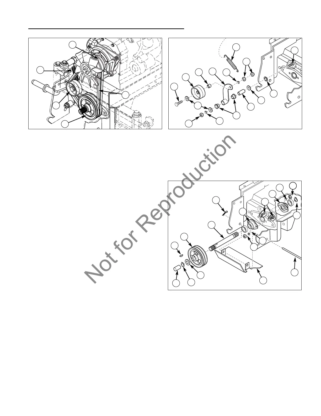
Belt, Pulley, and Drive Replacement
Figure 19. PTO Clutch Assembly – Typical
A. Capscrew G. Nuts
B. Idler Pulley H. Washer
C. Spacer (Pulley) I. Bushing
D. Idler Arm J. Spacer (Idler Arm)
E. Lockwasher K. Push Nut
F. Spring
A
G
Figure 18. PTO Clutch Assembly – Typical
A. Spring D. Lower PTO Pulley
B. PTO Clutch Pulley E. Idler Pulley
C. PTO Belts
PTO Drive Replacement
1. Park the tractor on a level surface.
2. Turn the ignition key switch to the OFF position,
remove the key, set the parking brake, and turn the
PTO switch off.
3. Disconnect the negative (-) battery cable (see
Section 7, ELECTRICAL SYSTEM SERVICE).
4. Disconnect spark plug wires to prevent the possibility
of accidental starting.
5. Use a spring puller or a small rope loop to release and
remove the PTO belt idler arm spring (A, Figure 18).
6. Remove the belts (C), one at a time, from the lower
pulley (D) and PTO clutch pulley (B).
7. Remove the cap (A, Figure 20) covering the shaft (F).
8. Remove the retainer (B) from both sides of the
shaft (F).
9. Remove the lower pulley (E) and washer (C) from the
shaft (F), then remove the shaft from the bearings (H).
Check bearings for slop or rough feel. Check shaft and
pulley for spline wear.
B
E
D
C
F
A
C
K
J
E
H
I
G
H
D
B
E
A
Figure 20. PTO Drive Pulley and Shaft – Typical
A. Cap H. Bearing
B. Retainer (E-Ring) I. Nut
C. Washer J. Lockwasher
D. Key K. Capscrew
E. Pulley (Lower) L. Rod
F. Shaft M. Guard
G. Cotter Pin
D
A
E
H
F
G
H
B
L
I
B
J
K
J
C
I
M
10. To replace the bearings, remove the nuts (I), lock-
washers (J), and capscrews (K) from the bearings
(H).
11. Assemble in reverse order of disassembly.
12. After securing clutch components, perform safety
checks (see Section 3, MAINTENANCE).
6. Remove the belts (C), one at a time, from the lower
PTO pulley (D) and PTO clutch pulley (B).
7. Remove the nut (G, Figure 19) and additional hard-
ware that is securing the idler arm (D) to the frame.
8. Remove the capscrew (A) and nuts (G) that secure
the idler pulley (B) to the idler arm (D).
9. Assemble in reverse order of disassembly.

 Loading...