14 Hood, Dash, & Foot Rest Service
Remove and Replace
14 - 10
A
B
C
D
A
A
Figure 17. Remove Tunnel Assembly
A. Taptite Screws C. Panel Fastener
B. Tunnel Assembly D. Foot Rest Pad
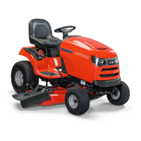
Figure 16. Remove Pedals
A. Gas Cap C. Brake Pedal Arm
B. Seat Deck D. Forward Ground Speed Pedal
A
B
C
D
Tunnel Assembly (Foot Rest) Removal
1. Turn the ignition key switch to the OFF position,
remove the key, set the parking brake, and turn the
PTO off.
2. Remove the seat deck assembly (see Section 15,
SEAT DECK & FUEL TANK SERVICE).
3. Disconnect the negative (-) battery cable (see
Section 7, ELECTRICAL SYSTEM SERVICE).
4. Remove the taptite screws (D, Figure 15) from the
brake pedal arm (B) and ground speed control pedal
arm (E). Remove the pedal arms from the tunnel
assembly.
5. Remove both foot rest pads (D, Figure 17) and panel
fasteners (C) by prying the foot rest pads up.
6. Remove the six small taptite screws (A) securing the
tunnel (B) to the frame.
7. Depress the differential lock pedal (B, Figure 18) and
remove the tunnel (B, Figure 17) from the frame.
Tunnel Assembly (Foot Rest) Replacement
1. Set the tunnel assembly (B, Figure 17) on the frame.
2. Install the six taptite screws (A) securing the tunnel
assembly (B) to the frame.
3. Install the forward ground speed pedal (D, Figure 16)
and brake pedal (C). Secure using the original hard-
ware.
4. Install the foot rest pads (D, Figure 17) and panel fas-
teners (C).
F
B
E
A
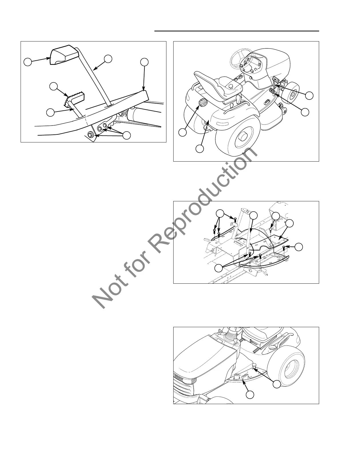
Figure 15. Brake and Speed Control Arms
A. Brake Pedal Pad D. Screws
B. Brake Pedal Arm E. Speed Control Arm
C. Foot Rest F. Speed Control Pad
D
C
Figure 18. Differential Lock Pedal
A. Foot Rest B. Lock Pedal
B
A