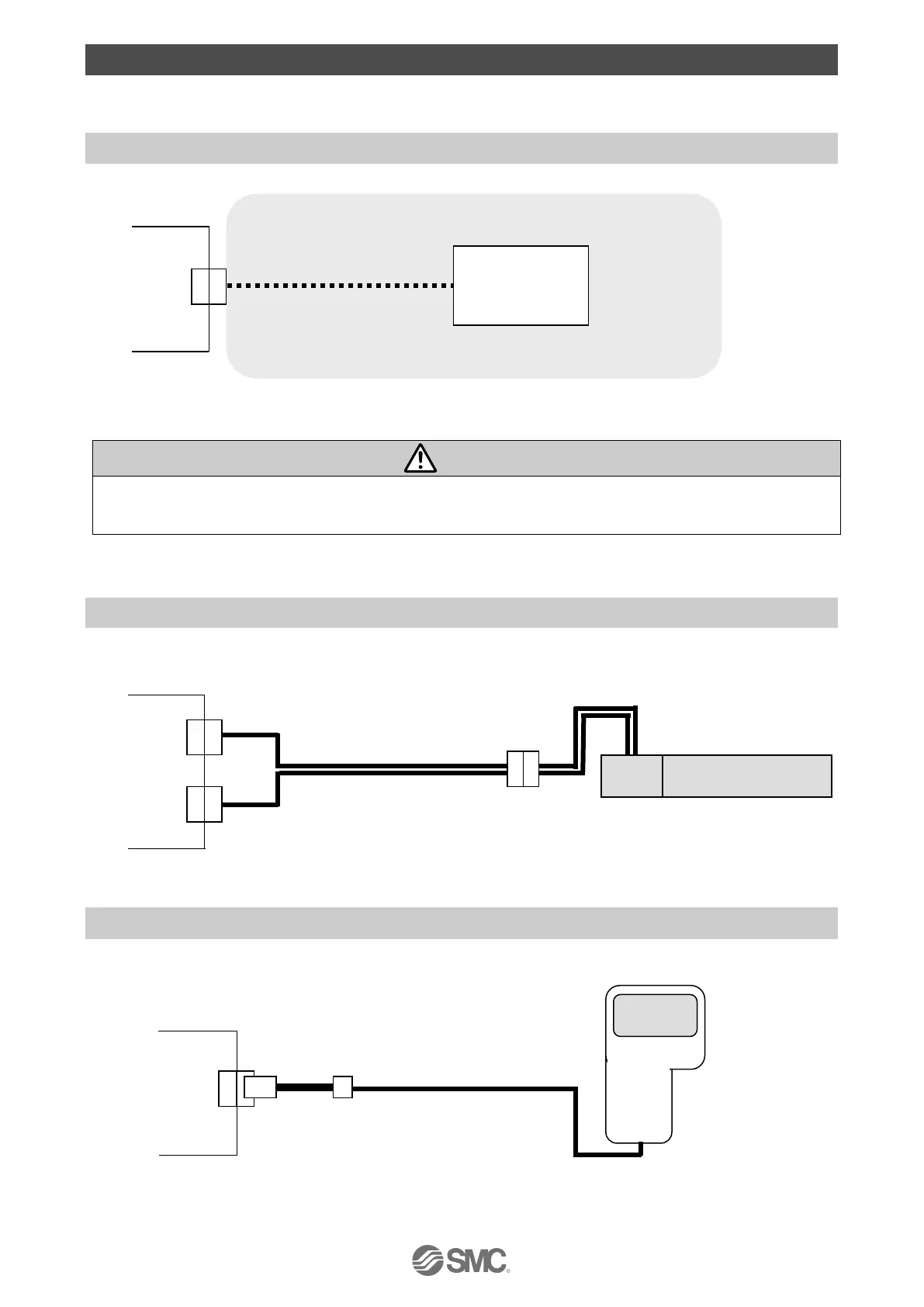
Controller power
supply 24 VDC
Power cable
(The 24 VDC power supply and the power cable should be obtained separately.)
4. External Wiring Diagram
Examples of standard wiring are shown for each connector of the controller.
4.1 PWR: Power connector
Controller
PWR
Please refer to "5. PWR: Power supply plug" for how to wire the PWR connector.
The controller power supply (24 VDC) do not use the power supply of "inrush current restraining
type".
4.2 MOT: Motor power connector and ENC: Encoder connector
Connect the controller and the electric actuator with the actuator cable (LE-CE-#-#).
Controller
ENC Actuator cable Electric Actuator
MOT
4.3 SI: Serial I/O connector
(1) Connection with the teaching box
(The 3m cable is provided.)
 Loading...


