- 51 -
No.JXC※-OMX0011-A
11. Operation instruction
The controller is operated by selecting step data preset in the controller using the parallel I/O signals.
The operating conditions are shown below.
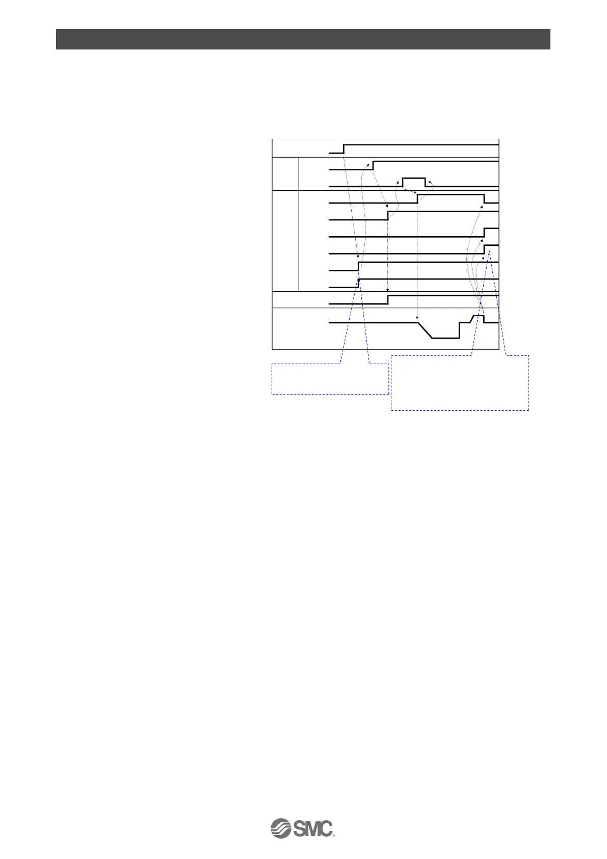
(1) Power on → Return to origin
- Procedures- - Timing chart Power on → Return to origin -
1) Apply the power.
↓
2) *ALARM is turned ON.
*ESTOP is turned ON.
↓
3) SVON is turned ON.
↓
4) SVRE is turned ON.
The time taken for SVRE output to
turn on depends on the electric
actuator type and the operating
conditions
The electric actuator with lock is
unlocked.
↓
5) SETUP is turned ON.
↓
6) BUSY is turned ON.
(The electric actuator moves.)
↓
7) SETON and INP are turned ON.
When the BUSY output is turned OFF, the return to origin operation has been completed.
If the electric actuator is within
the "In position" range, INP will
be turned ON but if not, it will
remain OFF.
 Loading...


