EasyManuals Logo
Home>SMC Networks>Controller>JXC51

SMC Networks JXC51 User Manual

Default Icon
78 pages
To Next Page IconTo Next Page
To Previous Page IconTo Previous Page
Page #8 background imageLoading...
Page #8 background image
- 7 -
No.JXC-OMX0011-A
Part No:LEC-W2-U
●Controller
communication cable
Part No:JXC-W2A-C
PC
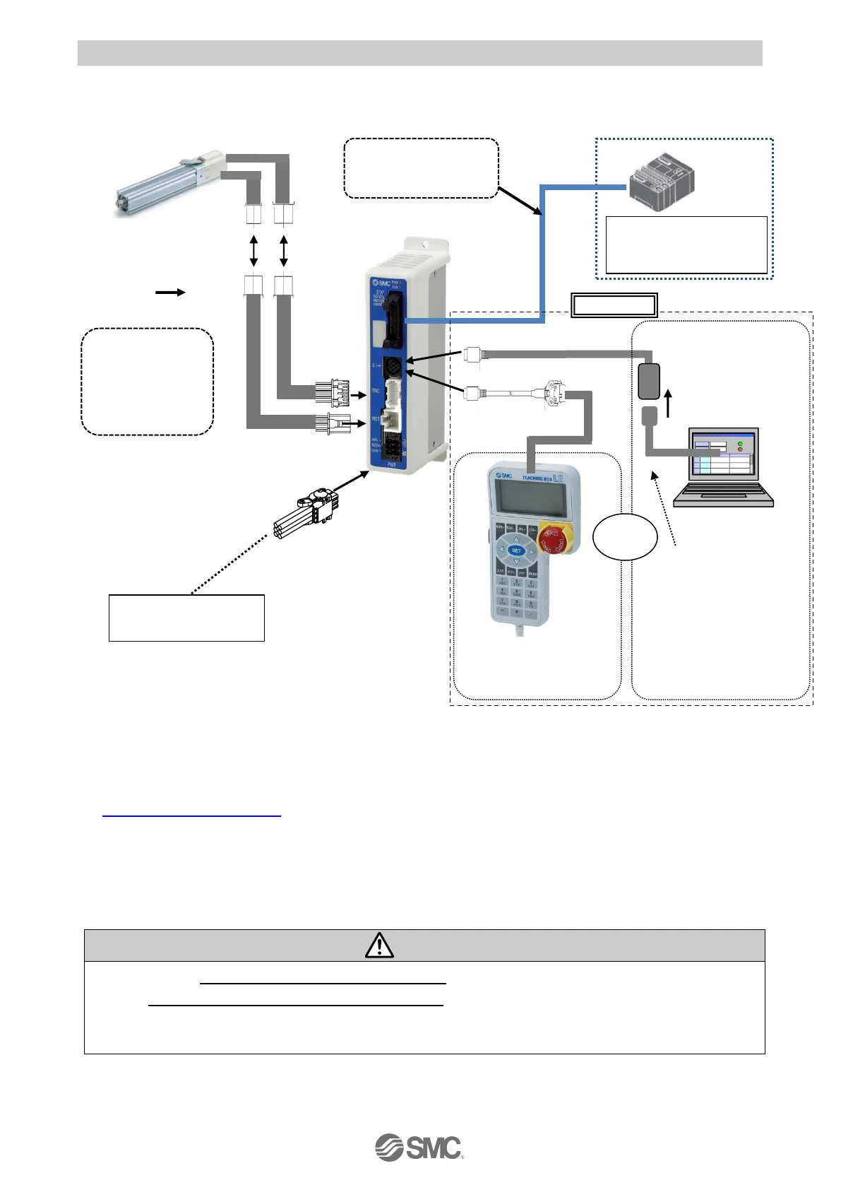
2.2 Product configuration
The product configuration of this controller is as follows.
Electric actuator
*1)
Prepared by user
P*1) *5)
Actuator cable
Part No
LE-CE-#-#
P*3)
●Power supply plug
(accessory)
Part No:
JXC-CPW
Applicable cable size
AWG20 (0.5mm
P2P
)
*1) These items are included when ordered using the part number for the electric actuator set.
*2) Please download the controller configuration software from the SMC website.
https://www.smcworld.com/
*3) 24 VDC power supply for controller input and 24 VDC power supply for parallel I/O signal should be
separated.
*5) PC is prepared by the user.
*6) Optional.
Warning
Refer to section "4. External Connection for wiring".
Refer to "13. Wiring of cables/Common precautions" when handling the wiring and cables.
Do not connect the teaching box, LAN equipment, or LAN cable directly to a PC.
Otherwise, the controller, PC or equipment may be damaged.
位置 速度
100 500
200
1000
50
200
1
2
3
在位
120.3
在速
200
mm
mm/ s
動作
設定
速度
100 500
200
1000
50
200
1
2
3
テスト
テスト
テスト
現在位
120.3
現在速
200
mm
mm/ s
動作中
アラー
モニタ
設定
PLC
*3)
Parallel I/O
Signal power supply
24 VDC
Controller power supply
24 VDC
Controller
●Teaching box
(with 3m cable)
Part No: LEC-T1-3#G#
or
Option
*5)
I/O cable
Part No: LEC-CN5-#
to SI
to ENC
to MOT
to PWR
●Conversion cable
Part No:P5062-5
*2) *4)

Table of Contents

Questions and Answers:

Question and Answer IconNeed help?

Do you have a question about the SMC Networks JXC51 and is the answer not in the manual?

SMC Networks JXC51 Specifications

General IconGeneral
BrandSMC Networks
ModelJXC51
CategoryController
LanguageEnglish

Related product manuals