- 37 -
●Byte1: Output port to which signal is allocated
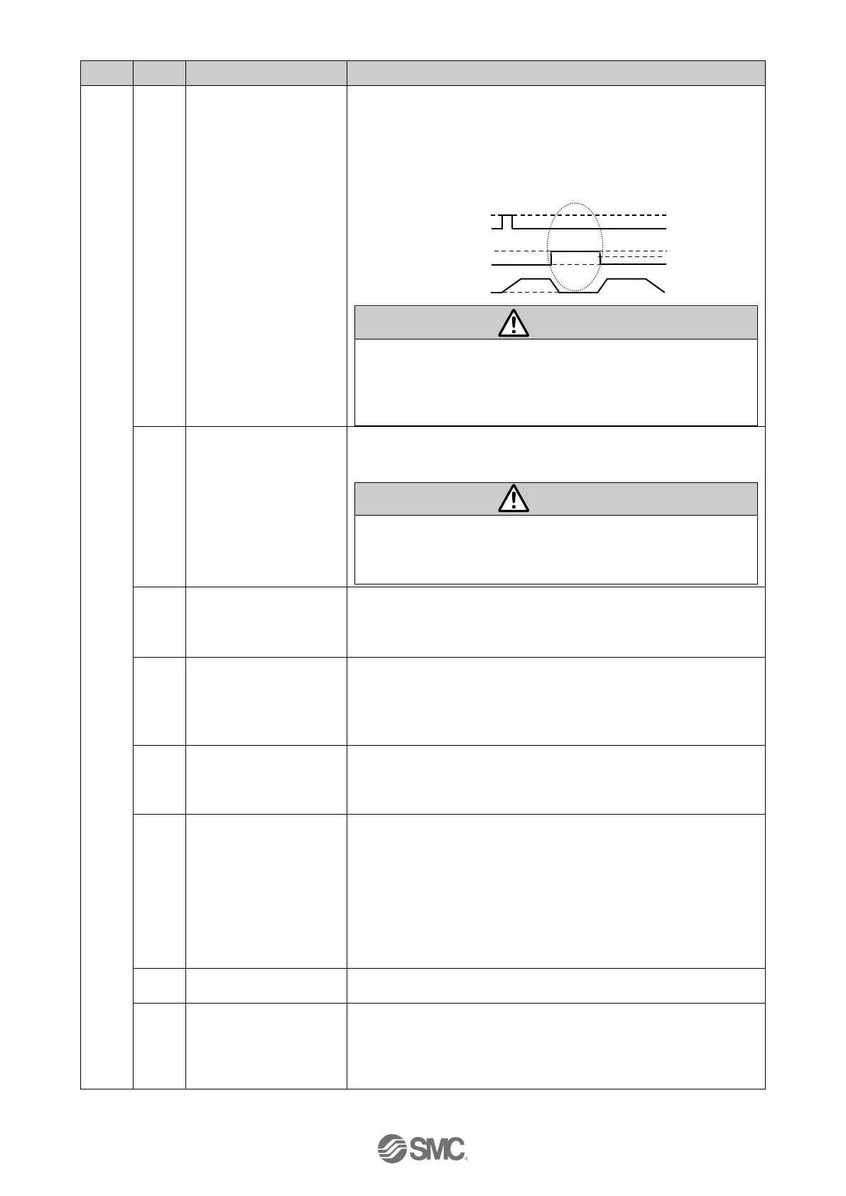
If “HOLD” is turned ON during operation, the speed decreases
at maximum deceleration set in the basic parameters until the
actuator stops. The remaining stroke will be on hold as long as
“HOLD” is ON and when “HOLD” is turned OFF, the actuator
restarts and travels for the remaining stroke.
- When “DRIVE” or “SETUP” is ON
(1) Do not turn on “SETUP”, “DRIVE”, “JOG+/JOG-“ or
Start flag when “HOLD” is ON. The actuator may make
unexpected movement.
(2) The signals are rendered invalid whilst “HOLD” is in
operation.
“SVON” signal turns the servo motor ON.
When “SVON” is ON, the servo motor will be turned ON.
When it is OFF, the servo motor will be turned OFF.
(1) When “SVON” is ON for the first time after supplying
power to the controller, the actuator moves several mm
to improve the control accuracy.
(2) When “SVON” is OFF, turn OFF “DRIVE” and “SETUP”.
When “DRIVE” is turned ON, the system scans “IN0” to “IN5”
and starts the operation of the actuator.6)
Then, when “DRIVE” is turned OFF, the number of the active
step data will be output via the “OUT0” to “OUT5” signals.
“RESET” is a signal to reset the alarm and the operation.
After “RESET”, the speed decreases at maximum
deceleration of the basic parameter until the actuator stops.
“INP” and “OUT0” to “OUT5” will be turned OFF (however, if the
actuator is stopped within the in-position range, “INP” will turn ON).
When “SVRE” is ON, the “SETUP” operation (return to origin
operation) will be performed. During the “SETUP” operation,
“BUSY” will turn ON. After completion of the “SETUP” operation,
“SETON” and “INP” will turn ON.
Jogging in the (-) direction.
The actuator moves when the signal is ON and stops when the
signal is OFF.
When the “FLGTH” (signal for switching Jogging and Inching)
is ON, movement towards the (-) side is made according to
the "JOG(-)" signal.
“INP” and “OUT0” to “OUT5” are OFF during Jogging/Inching.
When Jogging/Inching is completed, “INP” will turn ON, but
“OUT0” to “OUT5” will remain OFF.
Jogging in the (+) direction.
Operation is the same as “JOG(-)”. with "-" changed to "+"
FLGTH switches the function (Jogging and Inching) of
Jogging signal "JOG(-)" and "JOG(+)".
Inching starts when this signal is ON and when the Jogging
signal turns ON.
The Inching amount is set in the operation parameters.
6 Turn ON “DRIVE” when stopped. If ”DRIVE” is turned ON while operating, it may lead to unexpected operation.
 Loading...


