RadarW
Check a deviation of optical axis between AF illuminator and cam-
era image.
Mode CAMERA
Subject Flash adjustment box (Note 4)
Paper which reflection rate is
18% (Note 5)
(50 cm from the front of lens)
Measurement Point Displayed data of page: F,
address: 13
Measuring Instrument Adjusting remote commander
Adjustment Page F
Adjustment Address 10 to 16
Specified Value Data of page: F, address: 10 is
“00”
Note 1: Do not look directly into AF illumination which has not
been adjusted yet or failed in the adjustment abnormally.
Note 2: Perform checking by making the shooting surface of the
Flash adjustment box perpendicular to the optical axis of
the camera.
Note 3: Perform this checking in the Flash adjustment box.
Restrict external light to enter the Flash adjustment box
as less as possible.
Note 4: Refer to “4. Preparing the Flash adjustment box”.
(See page 6-7)
Note 5: Background paper (J-2501-130-A).
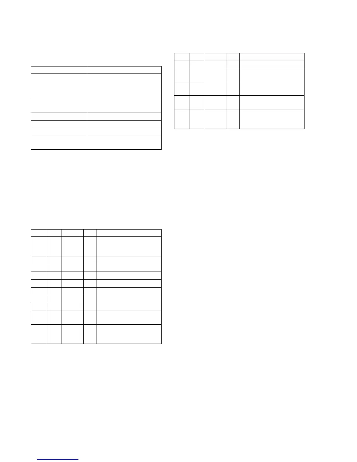
Adjusting method:
Order Page Address Data Procedure
1
Perform “Data setting during
camera system adjustment”.
(Refer to page 6-14)
2 F 15 Note down the data.
3 9 62 Note down the data.
4 9 83 Note down the data.
5 F 15 80 Press PAUSE button.
6 9 62 06 Press PAUSE button.
7 9 83 50 Press PAUSE button.
8 6 01 AF Press PAUSE button. (Note 6)
96 02
Check the data changes to
“01”.
10 F 13
Check the data.
00: Normal
FF: Defective
Note 6: The adjustment data will be automatically input to page:
F, address: 10 to 16.
Processing after Completing Adjustment:
Order Page Address Data Procedure
1 6 01 00 Press PAUSE button.
2F 15
Set data noted down at step 2,
and press PAUSE button.
39 62
Set data noted down at step 3,
and press PAUSE button.
49 83
Set data noted down at step 4,
and press PAUSE button.
5
Release the data setting per-
formed at step 1. (Refer to
page 6-14)

 Loading...