DSC-F717
6-49
COVER
COVER
2-3. SERVICE MODE
1. Setting the Test Mode
Page D Address 21
Data Function
00 Normal
05 Forced MOVIE mode power ON
07 Forced CAMERA mode power ON
08 Forced PLAY mode power ON
09 Forced SET UP mode power ON
• Before setting the data, select page: 0, address: 01, and set data:
01.
• For page D, the data set is recorded in the non-volatile memory
by pressing the PAUSE button of the adjusting remote com-
mander. In this case, take note that the test mode will not be
exited even when the main power is turned off.
• After completing adjustments/repairs, be sure to return the data
of this address to “00”, and press the PAUSE button of the ad-
justing remote commander.
Select page: 0, address: 01, and set data: 00.
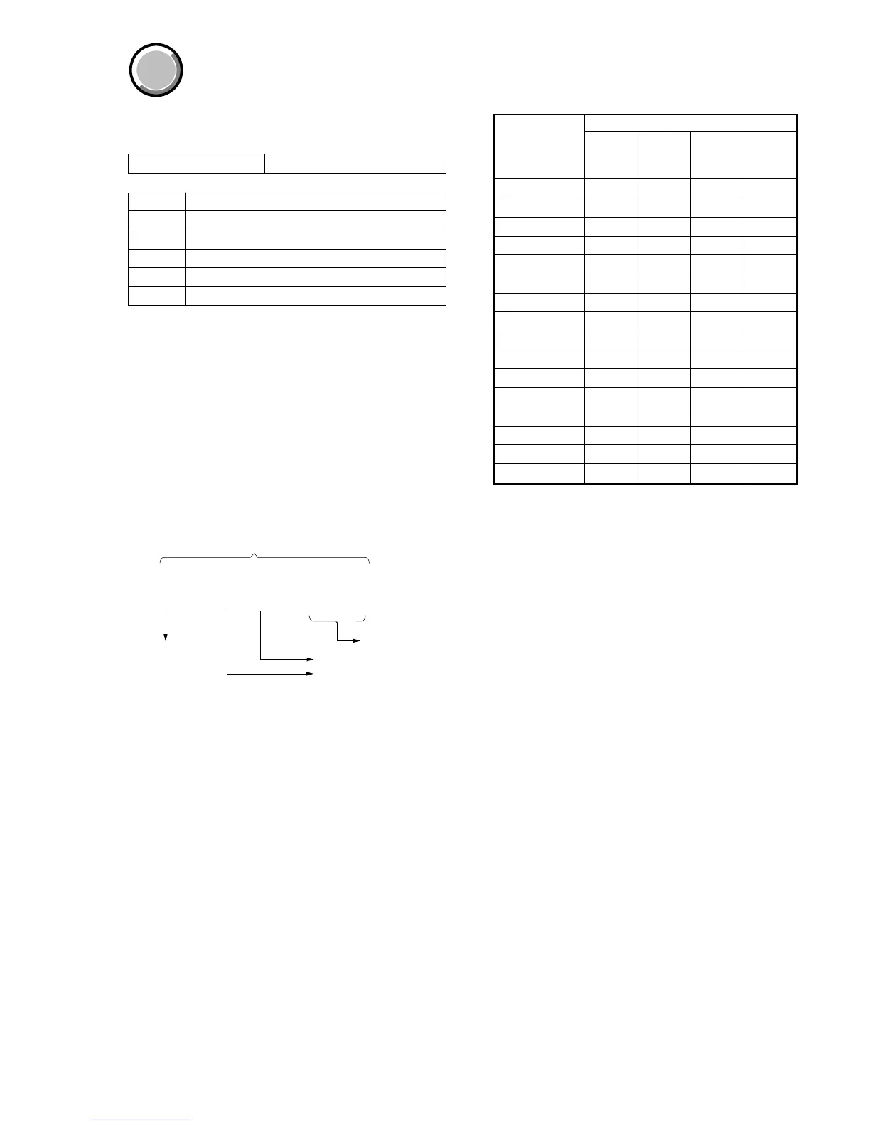
2. Bit Value Discrimination
Bit values must be discriminated using the display data of the ad-
justing remote commander for following items. Use the table be-
low to discriminate if the bit value is “1” or “0”.
Display on the Bit values
Adjusting bit3 bit2 bit1 bit0
remote or or or or
commander bit7 bit6 bit5 bit4
00000
10001
20010
30011
40100
50101
60110
70111
81000
91001
A (A)1010
B (b)1011
C (c)1100
D (d)1101
E (E)1110
F (F)1111
Example: If “8E” is displayed on the adjusting remote com-
mander, the bit values for bit7 to bit4 are shown in the
A column, and the bit values for bit3 to bit0 are shown
in the B column.
0 : 00 : 00
Page
bit7 to bit4 discrimination
bit3 to bit0 discrimination
Address
Display on the adjustilng remote commander
B
A

 Loading...