6
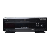
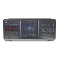
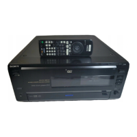
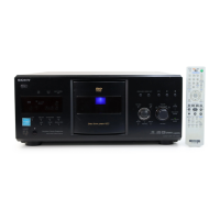
DVP-CX777ES
SECTION 1
SERVICING NOTES
The laser diode in the optical pick-up block may suffer electro-
static break-down because of the potential difference generated
by the charged electrostatic load, etc. on clothing and the human
body.
During repair, pay attention to electrostatic break-down and also
use the procedure in the printed matter which is included in the
repair parts.
The flexible board is easily damaged and should be handled with
care.
NOTES ON LASER DIODE EMISSION CHECK
The laser beam on this model is concentrated so as to be focused
on the disc reflective surface by the objective lens in the optical
pick-up block. Therefore, when checking the laser diode emis-
sion, observe from more than 30 cm away from the objective lens.
NOTE OF REPLACING THE MB BOARD
When replacing the MB board, since the adjustment value is not
set up correctly, “Drive Auto Adjustment” can’t be performed.
In this case, initialize Memory in the following procedures.
Procedure:
1. Set the test mode. (See page 23)
2. Press the [2] key of the remote commander, and set the “DRIVE
MANUAL OPERATION”. (See page 29)
3. Press the [6] key of the remote commander, and set the “2-6,
Memory Check”. (See page 32)
4. Press the [CLEAR] key of the remote commander, and initial-
ize Memory.
NOTES ON HANDLING THE OPTICAL PICK-UP
BLOCK OR BASE UNIT
CHECK OF POWER BOARD WITH THE POWER ON
It is possible to analyze the defect with only POWER board power
ON.
Procedure:
1. Set to power OFF state.
2. Remove the connector from CN201 on the POWER board.
3. Short between CN201 pin 1 (P-CONT) and CN201 pin qa
(EVER+3.3V) on the POWER board.
4. Turn the power ON.
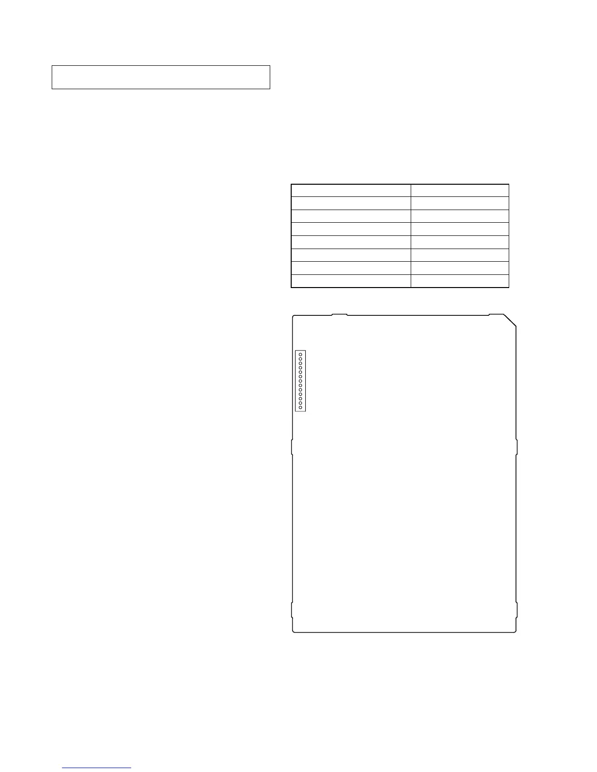
5. Confirm that the voltage value of CN201 each pin on the
POWER board satisfy following value .
CN201 Pin Voltage Value
pin 2 (EVER–11V) –11V
pin 3 (SW–11V) –11V
pin 6, 7 (SW+11V) +11V
pin 8 (SW+3.3V) +3.3V
pin qa (EVER+3.3V) +3.3V
pin qs (SW+5V) +5V
pin qd (EVER+5V) +5V
– POWER Board (Conductor Side) –
CN201
13
1
Ver 1.1
 Loading...