7-3
4. Checking Component Video Output R-Y
<Purpose>
This checks component video output R-Y. If it is incorrect, cor-
rect colors will not be displayed when connected to, for instance,
projector.
Mode Video level adjustment in test mode
Signal Color bars
Test point
COMPONENT VIDEO OUT (R-Y)
connector (75 Ω terminated)
Instrument Oscilloscope
Specification 700 ± 50 mVp-p
Checking method:
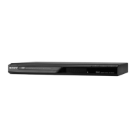
1) Confirm that the R-Y level is 700 ± 50 mVp-p.
Figure 7-4
5. Component Video Output Y Level Adjustment
(VP-52 BOARD)
<Purpose>
This adjustments component video output Y. If it is incorrect,
correct brightness will not be attained when connected to, for in-
stance, projector.
Mode Video level adjustment in test mode
Signal Color bars
Test point
COMPONENT VIDEO OUT (Y)
connector (75 Ω terminated)
Instrument Oscilloscope
Adjusting element RV101
Specification 1.00 Vp-p
Adjusting method:
1) In the test mode initial menu “6” Video Level Adjustment, set
so that color bars are generated.
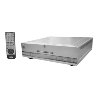
2) Adjust the RV101 to attain 1.00 Vp-p
Figure 7-5
700 ± 50 mVp-p
+ 0.04
– 0.02
+ 0.04
– 0.02
1.00 Vp-p
+ 0.04
– 0.02
6. Progressive Video Output Level Adjustment
(VP-52 BOARD)
<Purpose>
This adjustments progressive video output. If it is incorrect, cor-
rect brightness will not be attained when connected to, for instance,
projector.
Mode Video level adjustment in test mode
Signal Color bars
Test point
COMPONENT VIDEO OUT (Y)
connector (75 Ω terminated)
Instrument Oscilloscope
Adjusting element RV401
Specification 1.00 Vp-p
Adjusting method:
1) In the test mode initial menu “7” Prog Level Adjustment, set
so that color bars are generated.
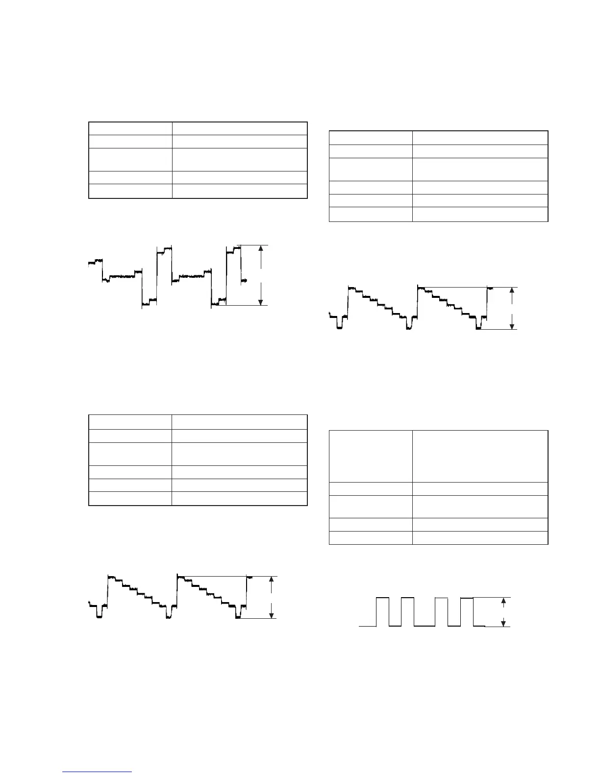
2) Adjust the RV401 to attain 1.00 Vp-p
Figure 7-6
7. Checking RGB Output R (AEP, UK Model)
<Purpose>
This checks RGB output R. If it is incorrect, pictures will not be
displayed correctly in spite of connection to the TV with an EURO
AV connecting cord.
Mode
In test mode,
Push
[0] for Syscon Diagnosis and
push [8] for Video and push [8] and
[ENTER] for Euro TV Check and
push [NEXT] twice for RGB out
Signal Color bars
Test point
EURO AV 1 (RGB)-TV connector
pin qg (75 Ω terminated)
Instrument Oscilloscope
Specification 700 ± 50 mVp-p
Checking method:
1) Confirm that the R level is 700 ± 50 mVp-p.
Figure 7-7
+ 0.04
– 0.02
+ 0.04
– 0.02
700 ± 50 mVp-p
1.00 Vp-p
+ 0.04
– 0.02
 Loading...