7-4
10.Checking S Video Output S-C
<Purpose>
This checks whether the S-C satisfies the NTSC Standard. If it is
not correct, the colors will be too dark or light.
Mode Video level adjustment in test mode
Signal Color bars
Test point
S VIDEO OUT (S-C) connector
(75 Ω terminated)
Instrument Oscilloscope
Specification
A = 286 ± 30 mVp-p (NTSC)
A = 300 ± 100 mVp-p (PAL)
Checking method:
1) In the test mode initial menu “6” Video Level Adjustment, set
so that color bars are generated.
2) Confirm that the S-C burst is “A”.
Figure 7-10
A
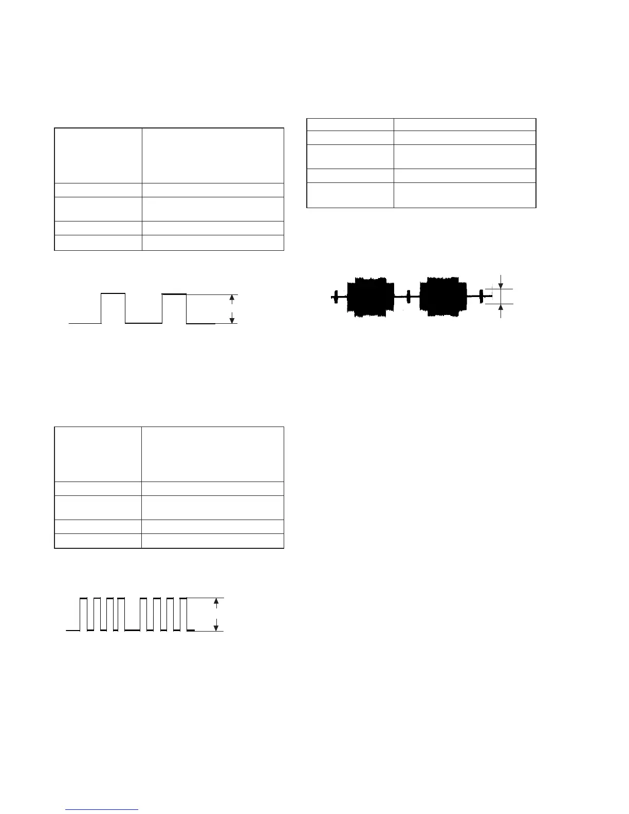
8. Checking RGB Output G (AEP, UK Model)
<Purpose>
This checks RGB output G. If it is incorrect, pictures will not be
displayed correctly in spite of connection to the TV with an EURO
AV connecting cord.
Mode
In test mode,
Push [0] for Syscon Diagnosis and
push [8] for Video and push [8] and
[ENTER] for Euro TV Check and
push [NEXT] twice for RGB out
Signal Color bars
Test point
EURO AV 1 (RGB)-TV connector
pin qa (75 Ω terminated)
Instrument Oscilloscope
Specification 700 ± 50 mVp-p
Checking method:
1) Confirm that the G level is 700 ± 50 mVp-p.
Figure 7-8
9. Checking RGB Output B (AEP, UK Model)
<Purpose>
This checks RGB output B. If it is incorrect, pictures will not be
displayed correctly in spite of connection to the TV with an EURO
AV connecting cord.
Mode
In test mode,
Push [0] for Syscon Diagnosis and
push [8] for Video and push [8] and
[ENTER] for Euro TV Check and
push [NEXT] twice for RGB out
Signal Color bars
Test point
EURO AV 1 (RGB)-TV connector
pin 7 (75 Ω terminated)
Instrument Oscilloscope
Specification 700 ± 50 mVp-p
Checking method:
1) Confirm that the B level is 700 ± 50 mVp-p.
Figure 7-9
700 ± 50 mVp-p
700 ± 50 mVp-p
 Loading...