FST-GTK11iP/GTK33iP/RDH-GTK11iP/GTK33iP
28
total twenty bosses
3
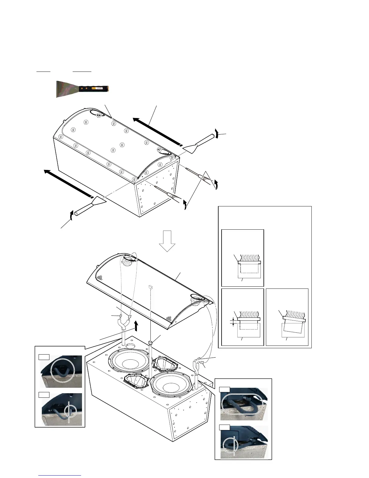
2 Insert the jig into a space and raise
the front panel assy.
Note 1: When using a jig, please work
so as not to injure front panel
assy and SPK box assy.
2 Insert the jig into a space and raise
the front panel assy.
Note 1: When using a jig, please work
so as not to injure front panel
assy and SPK box assy.
3 All bosses are removed while moving jig in the direction
of the arrow, and front panel assy is removed.
1 Insert the flat-blade driver into a side space
and raise the front panel assy.
– Bottom front view –
Note 2:
When you install the connector, please
install themcorrectly.
There is a possibility that this machine
damages when not correctly installing it.
Insert is shallow
Insert is straight
to the interior.
connector
Insert is incline
connector
connector
connector
connector connector
NG
OK
NG
7 front panel assy
6 terminal (red)
6 terminal (red)
6 terminal (black/red)
6 terminal (black/red)
4 Remove the front panel assy
in the direction of an arrow.
:ire VettinJ
:ire VettinJ
OK
NG
OK
NG
5 connector
(CN551)
2-20. FRONT PANEL ASSY
• JIG
When disassembling the set, use the following jig (for speaker
removal).
Part No. Description
J-2501-238-A JIG FOR SPEAKER REMOVAL
 Loading...