5-6. TRIAX Transmission System Adjustment
5-6-1. 1.0-MHz Modulation Circuit Adjustment
Frequency Adjustment
Preparation
• Disconnect the camera.
• If the camera is connected, turn off the CAMERA POWER switch on the inside panel.
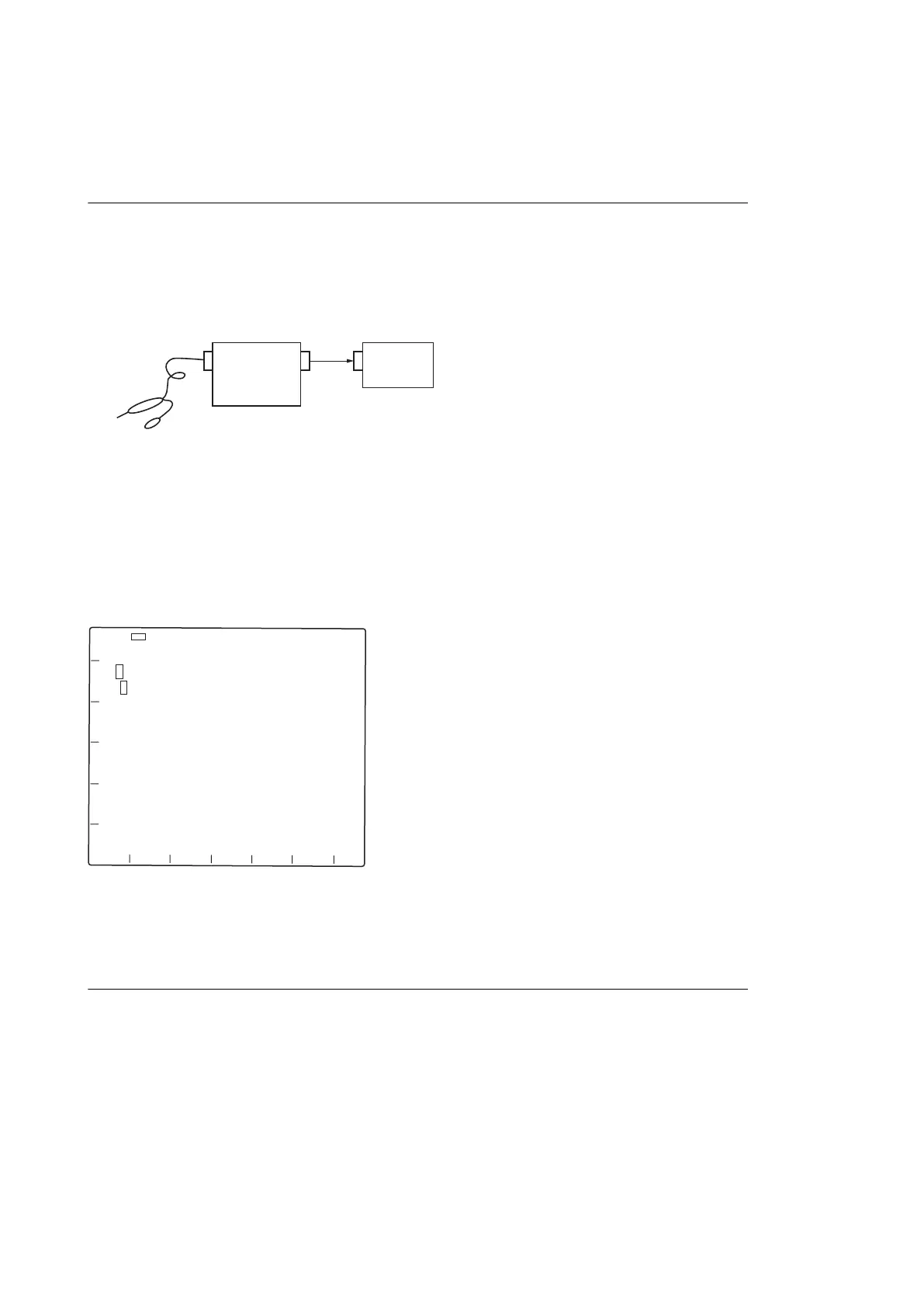
• Connect the measuring equipment as shown in the figure.
CH2
Oscilloscope
Frequency counter
Probe
IN
CH2
OUT
IN
Adjustment
Equipment: Frequency counter
Test Point:
• TP1501 (A-2)/DM-152 board
• GND: E14 (B-1)/DM-152 board
Adjusting Point: LV1501 (A-2)/DM-152 board
Specification: 1000 ±5 kHz
DM-152 board (Side A)
A B C D E F G
1
2
3
4
5
6
E14
TP1501
LV1501
5-6-2. 1.4-MHz Demodulation Circuit Adjustment
Preparation
• Disconnect the coaxial cable from the connector CN3901 on the DM-152 board, and then connect the FM signal
generator to CN3901.
• FM signal generator settings
Carrier frequency: 1.4 MHz
AF frequency: 1 kHz
Output level: -15 dBm
Dev: ±0 kHz
HXCU-TX70
5-14
 Loading...