5-2. Audio System Adjustment
5-2-1. RTS Intercom Adjustment Check
Precautions
• This adjustment is described on condition that the audio oscillator output impedance is 600 Ω.
• Potentiometers RV1050 and RV1051 on the DPR-361 board have been adjusted according to the customer’s system.
Check this adjustment only when the system intercom output is repaired.
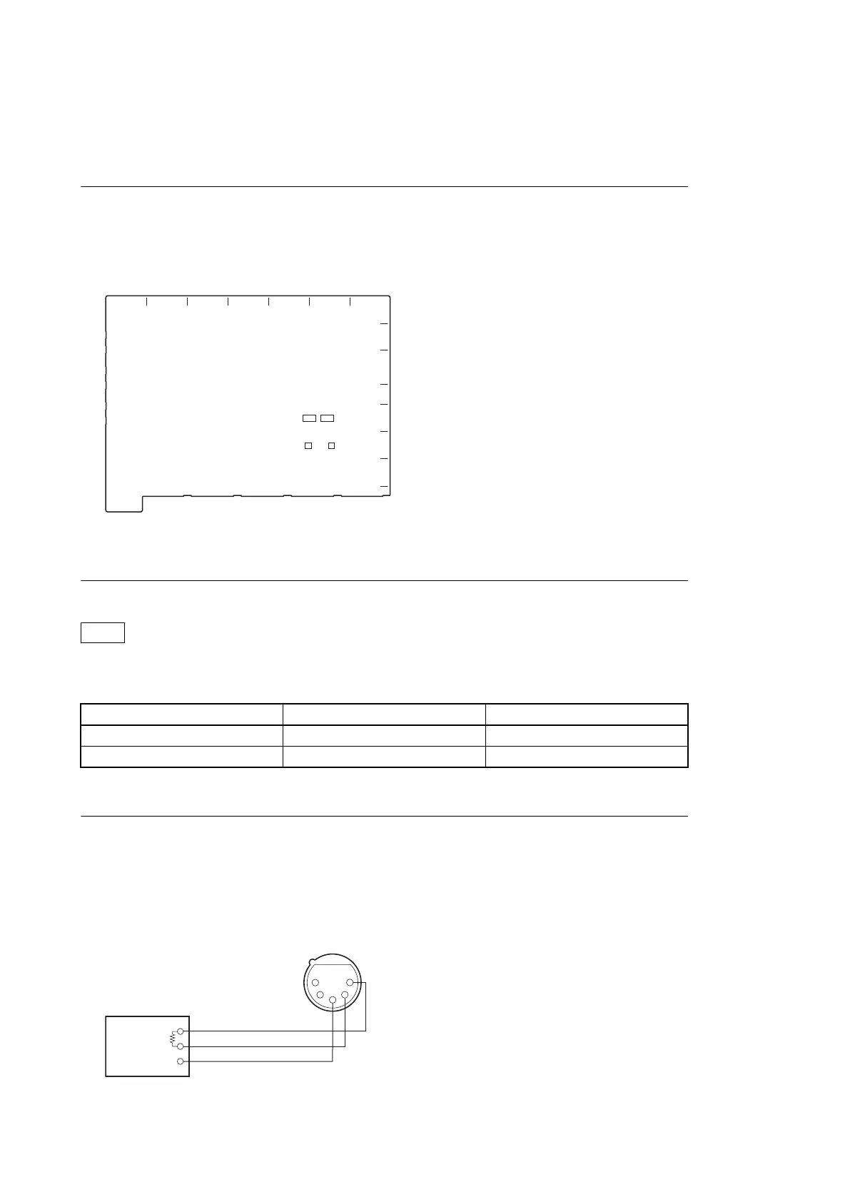
DPR-361 board (Side A)
RV1050
RV1051
A B C D E F G
1
2
3
4
5
6
7
TP1051
TP1050
8
Preparation
Note
Remove the DM-152 board and make adjustment.
CCU CONFIGURATION menu setting
Page name Item Settings
C06: INTERCOM SYSTEM I/F RTS
C07: FRONT INCOM INCOM MIC CARBON
Check (PROD CANCEL)
1. Set the INTERCOM switch on the front panel to PROD.
2. Input a sine wave (1 kHz, 220 mVp-p (-20 dBu)) to pin 2 (X), pin 1 (Y), and pin 3 (G) of the INTERCOM connector
from the audio oscillator.
600 Ω
Audio oscillator
INTERCOM connector
(Front panel)
GND
1
2
3
4
5
HXCU-TX70
5-3
 Loading...