Component Access / Removal
600 Series
(Prior to #1810000)
7-29
#3756270 - Revision B - January, 2006
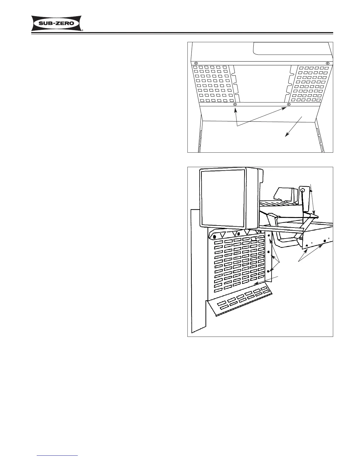
Figure 7-56. Model 690 Icemaker and Carriage Assembly
Ice Level Arm
Assembly
Icemaker Carriage
Assembly
Screws
Freezer Lower Evaporator Cover (Model 690)
The lower evaporator cover assembly has two pegs at
the rear which fit into pockets in the rear wall. Snap
pins toward the front sides of the cover slide into pock-
ets in the side wall.
To access and remove the lower evaporator cover
assembly, the juice can rack, upper front panel, evapo-
rator front cover and rear duct will need to be removed
first. Now, pull the snap pins out of the pockets in the
side walls and lean the evaporator cover down. Then,
disconnect the electrical leads to the lighting and pull
the assembly forward. (See Figure 7-55)
Icemaker Carriage Assembly (Model 690)
The icemaker carriage assembly is secured to the side
wall by three screws, and three screws at the rear wall.
To access and remove the icemaker carriage assembly,
the juice can rack, upper front cover, evaporator front
cover, rear duct and lower evaporator cover assembly
will need to be removed first. Now, extract the mount-
ing screws from the rear and side walls. Then, pull the
carriage assembly down slightly and disconnect the
electrical leads to the icemaker. (See Figure 7-56)
Icemaker (Model 690)
The icemaker is attached to the icemaker carriage
assembly. To access and remove the icemaker, the
juice can rack, upper front panel, evaporator front cover,
rear duct, lower evaporator cover assembly and ice-
maker carriage assembly will need to be removed first.
Then, extract the mounting screw which secure the ice-
maker to the carriage assembly. (See Figure 7-56)
Figure 7-55. Model 690 Rear Duct Removal
Screws
Rear Duct
 Loading...