Component Access / Removal
600 Series
(Prior to #1810000)
7-38
#3756270 - Revision B - January, 2006
Evaporator (Models 601R, 601F)
NOTE: Evaporator fins are sharp and could cause
minor personal injury.
NOTE: When replacing the evaporator, the filter-drier
must also be replaced.
NOTE: When removing the evaporator from a model
601F, the defrost heater and defrost terminator must be
removed first.
The evaporator is attached to the rear wall, behind the
evaporator cover. After capturing the refrigerant from
the sealed system, remove the screws which secure
the evaporator to the rear wall. Pull the bottom of the
evaporator up while rotating the heat exchanger out.
Now, un-braze or cut the evaporator inlet and outlet tub-
ing, and pull evaporator from compartment. (See
Figure 7-69)
Heat Exchanger (Models 601R, 601F)
NOTE: When replacing a heat exchanger, the filter-drier
must also be replaced.
NOTE: It is not necessary to pull the unit from its instal-
lation in order to replace the heat exchanger. The heat
exchanger travels through a tubing channel which is
foamed into the rear wall of the unit.
To remove the heat exchanger, the compressor area
and evaporator area will need to be accessed, and the
refrigerant captured from the sealed system. Now,
extract the screws which secure the evaporator to the
rear wall, and pull the left side of the evaporator up and
out. Un-braze or cut the evaporator inlet and outlet tub-
ing, and pull evaporator from compartment. Now, pull
the armaflex from the heat exchanger in the compres-
sor area, and cut the heat exchanger in the compressor
area as close as possible to the tubing channel. cut the
suction line from the compressor suction extension, and
the capillary tube from the drier. Then, pull the remain-
ing heat exchanger up and out of the tubing channel.
(See Figures 7-68 and 7-69)
NOTE: When replacing the heat exchanger, it is recom-
mended to attach it at the evaporator end first, then
feed the heat exchanger down through the tubing chan-
nel.
One end of heat exchanger is connected to evapo-
rator. Evaporator fins are sharp. One end of heat
exchanger is connected to compressor and filter
drier. Compressor and tubing may be hot.
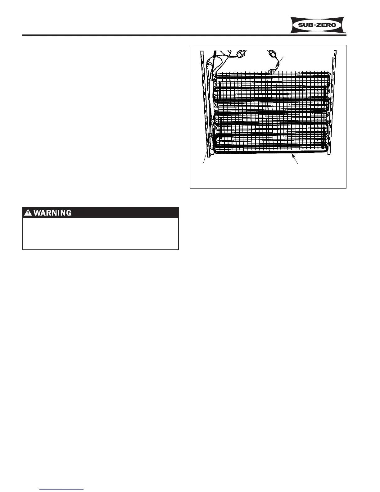
Figure 7-69. Model 601R, 601F Evaporator Area
NOTE: 601R is same, minus heater and terminator.
Heat Exchanger
Defrost Heater
Defrost Terminator
 Loading...