Component Access / Removal
600 Series
(Prior to #1810000)
7-36
#3756270 - Revision B - January, 2006
SEALED SYSTEM COMPONENTS
This section explains how to remove sealed system
components during a sealed system repair. In most
cases it is necessary to remove primary parts, and in
some cases mechanical & electrical components, in
order to gain access to these components. The manner
in which this section was written assumes that the
PRIMARY PART REMOVAL and MECHANICAL &
ELECTRICAL COMPONENT REMOVAL sections have
been studied and understood. If necessary, refer to
these sections in this manual before attempting to
remove sealed system components.
When possible, units with similar component removal
procedures were grouped together under the appropri-
ate heading. The units covered will be listed between
brackets after the heading.
NOTE: 600 Series units are produced without process
valves on the compressor and filter-driers. Solder-on
process valves must be installed in order to service the
sealed system. Sub-Zero does not authorize the use of
bolt-on saddle valves.
Filter-Drier (Models 601R, 601F)
NOTE: Compressor and tubing may be hot and could
cause minor personal injury.
NOTE: To access the filter-drier it is recommended, but
not necessary, to remove the top section of the unit
grille assembly after removing the bottom section.
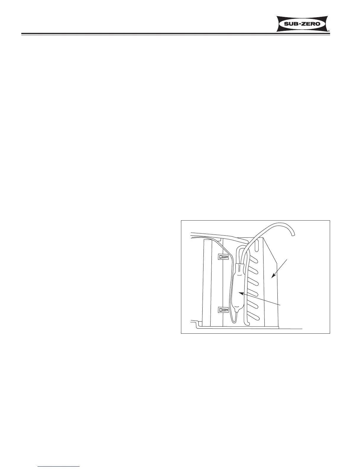
The filter-drier is attached to the condenser outlet. (See
Figure 7-67) To remove a filter-drier, first remove the
lower sections of the unit grille. Then, after capturing
the refrigerant from the sealed system, use a file to
score a line around the capillary tube approximately
one inch from the filter-drier outlet. Fatigue the capillary
tube at this line until it separates. Then, with a tube
cutter, cut the filter-drier inlet tube.
NOTE: Check the end of the remaining capillary tube
for internal burrs. If burrs exist or tubing has been
pinched closed while fatiguing, re-score capillary tube
approximately one inch from the end. Then, fatigue the
capillary tube at this new line until it separates, and
recheck.
NOTE: When installing the replacement filter-drier,
insert capillary tube until it touches the screen. Then,
pull capillary tube out away from the screen approxi-
mately 3/8" before brazing.
NOTE: The filter-drier outlet must be facing downward
in order to function properly (See Figure 7-67).
Figure 7-67. Model 601R, 601F Filter-Drier Location &
Position
Condenser
Filter-Drier
 Loading...