45
Chapter 2: Installation
J7 J8
FAN4
JPWR2
JPWR1
JPL1
JPL3
I-SATA3
I-SATA2
JSD2
JSD1
JL1
LAN 1/3
LAN 2/4
USB 6/7
(3.0)
COM 1
JOH1
JUIDB1
DIMMB2
DIMMB1
DIMMA2
DIMMA1
J23
SP1
USB 2/3
JI2C2
JI2C1
JPB1
JPME2
JPG1
BAR CODE
MAC CODE
IPMI CODE
I-SGPIO2
I-SGPIO1
Intel PCH
USB 0/1
IPMI_LAN
VGA
LED BMC
COM2
JPL2
JPL4
JPI2C1
FAN1
FAN2
LED PWR
JSTBY1
JWD1
FAN3
FANA
JF1
USB 8/9
(3.0)
USB 10
(3.0)
USB 4/5
JTPM1
JBT1
JIPMB1
JD1
JBR1
PCH SLOT4 PCI-E 3.0 x4in x8
CPU SLOT5 PCI-E 3.0 x8
CPU SLOT6 PCI-E 3.0 x8in x16
BIOS
LICENSE
BMC
LE1
I-SATA6
I-SATA5
I-SATA4
I-SATA1
I-SATA0
LE3
X11SSH-F/-LN4F
REV:1.01
Designed in the USA
BT1
CPU
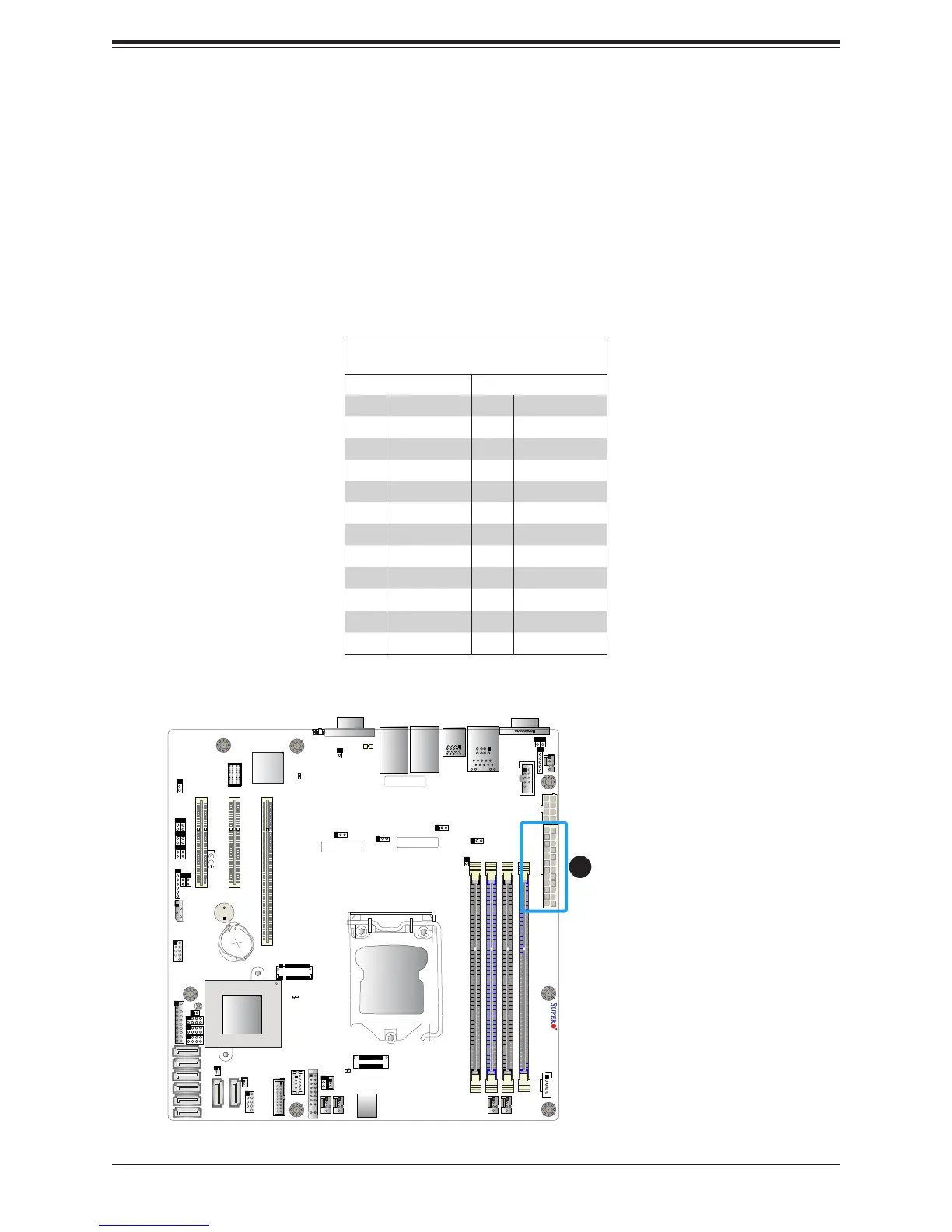
2.7 Connectors
Power Connections
Main ATX Power Supply Connector
The primary power supply connector (JPWR1) meets the ATX SSI EPS 12V specication.
You must also connect the 8-pin (JPWR2) processor power connector to your power supply.
ATX Power 24-pin Connector
Pin Denitions
Pin# Denition Pin# Denition
13 +3.3V 1 +3.3V
14 -12V 2 +3.3V
15 Ground 3 Ground
16 PS_ON 4 +5V
17 Ground 5 Ground
18 Ground 6 +5V
19 Ground 7 Ground
20 Res (NC) 8 PWR_OK
21 +5V 9 5VSB
22 +5V 10 +12V
23 +5V 11 +12V
24 Ground 12 +3.3V
Required Connection
1. 24-Pin ATX Main PWR
1

 Loading...


