53
Chapter 2: Installation
J7 J8
FAN4
JPWR2
JPWR1
JPL1
JPL3
I-SATA3
I-SATA2
JSD2
JSD1
JL1
LAN 1/3
LAN 2/4
USB 6/7
(3.0)
COM 1
JOH1
JUIDB1
DIMMB2
DIMMB1
DIMMA2
DIMMA1
J23
SP1
USB 2/3
JI2C2
JI2C1
JPB1
JPME2
JPG1
BAR CODE
MAC CODE
IPMI CODE
I-SGPIO2
I-SGPIO1
Intel PCH
USB 0/1
IPMI_LAN
VGA
LED BMC
COM2
JPL2
JPL4
JPI2C1
FAN1
FAN2
LED PWR
JSTBY1
JWD1
FAN3
FANA
JF1
USB 8/9
(3.0)
USB 10
(3.0)
USB 4/5
JTPM1
JBT1
JIPMB1
JD1
JBR1
PCH SLOT4 PCI-E 3.0 x4in x8
CPU SLOT5 PCI-E 3.0 x8
CPU SLOT6 PCI-E 3.0 x8in x16
BIOS
LICENSE
BMC
LE1
I-SATA7
I-SATA6
I-SATA5
I-SATA4
I-SATA1
I-SATA0
LE3
X11SSH-F/-LN4F
REV:1.01
Designed in the USA
BT1
CPU
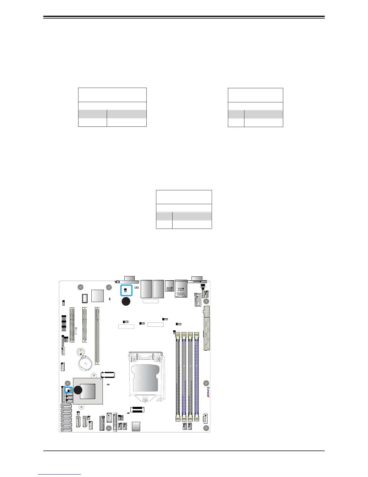
Chassis Intrusion
A Chassis Intrusion header is located at JL1 on the motherboard. Attach the appropriate cable
from the chassis to inform you of a chassis intrusion when the chassis is opened. Refer to
the table below for pin denitions.
Chassis Intrusion
Pin Denitions
Pin# Denition
1 Intrusion Input
2 Ground
1
2
1. Overheat/Fan Fail LED
Header
2. Chassis Intrusion
Overheat LED
Pin Denitions
Pin# Denition
1 5vDC
2 OH Active
Overheat/Fan Fail LED Header
The JOH1 header is used to connect an LED indicator to provide warnings of chassis
overheating and fan failure. This LED will blink when a fan failure occurs. Refer to the tables
below for pin denitions.
Overheat LED Header
Status
State Denition
Solid Overheat
Blinking Fan Fail

 Loading...


