AN650/AK7 (’07-MODEL) 21
“C41” (P2505) ECM/PCM POWER INPUT CIRCUIT MALFUNCTION
"
INSPECTION
Step 1 (When indicating C41:)
1) Turn the ignition switch OFF.
2) Remove the front panel. (#AN650K3 9-8)
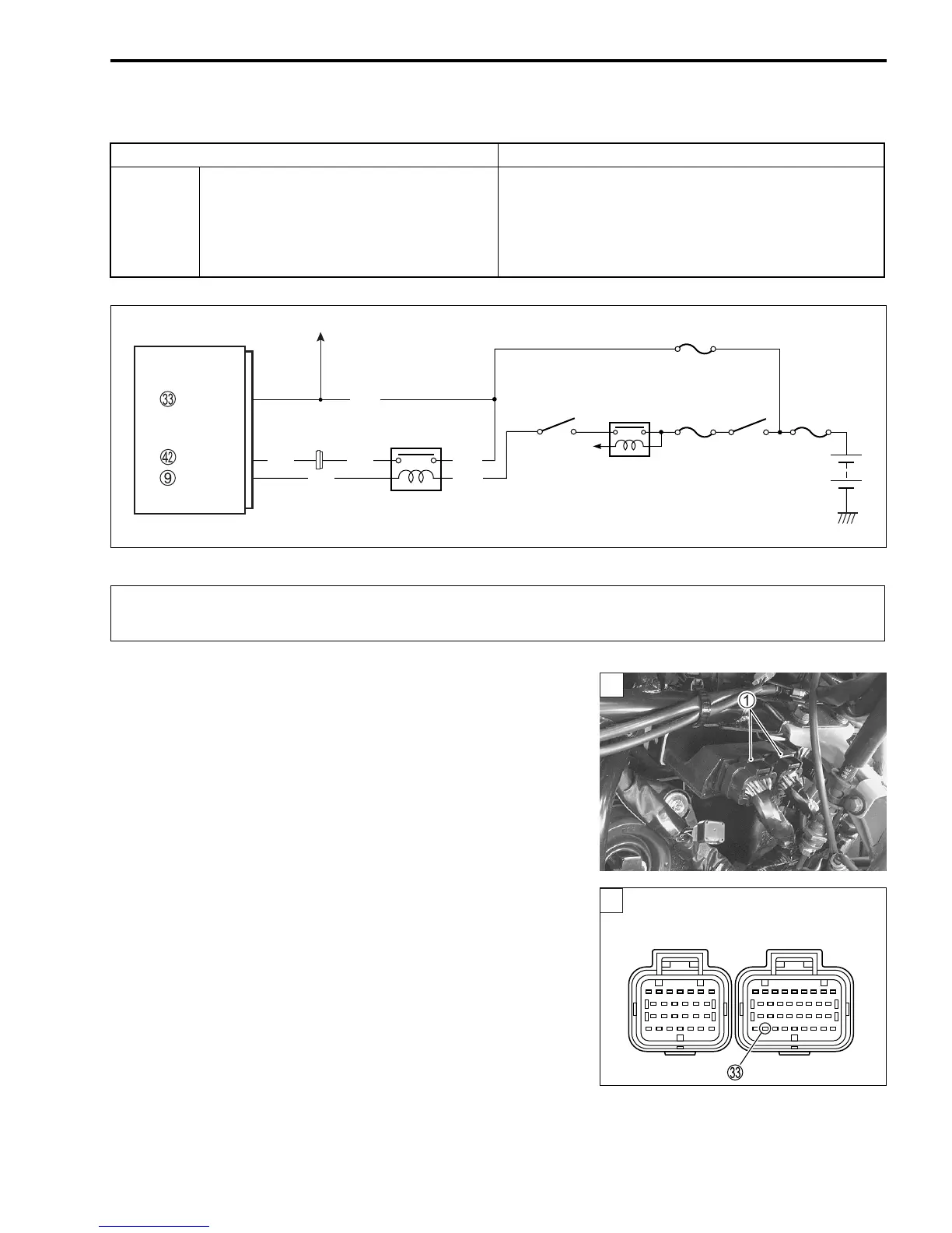
3) Check the ECM couplers
1 for loose or poor contacts.
If OK, then measure the ECM input voltage.
4) Disconnect the ECM couplers.
5) Measure the voltage between terminal
W and ground.
$ ECM input voltage: Battery voltage
! 09900-25008: Multi-circuit tester set
09900-25009: Needle pointed probe set
' Tester knob indication: Voltage (()
DETECTED CONDITION POSSIBLE CAUSE
C41
(P2505)
No voltage is applied to the ECM,
although the ignition switch is turned
ON.
• Lead wire/coupler connection of ECM terminal to
fuel fuse
•Fuel fuse
• Battery voltage to ECM (BATT) shorted to ground
or open
ECM
Side-stand
relay
Engine stop
switch
FP relay
Ignition
switch
Y/R
VM
BATT
FP Relay
R/BI
O/W
Y/Bl
To side-stand
switch
R/Bl
To Speedometer
Y/G
When using the multi-circuit tester, do not strongly touch the terminal of the ECM coupler with
a needle pointed tester probe to prevent the terminal damage or terminal bend.
1
ECM coupler (Harness side)
SAMPLE
 Loading...


