AN650/AK7 (’07-MODEL) 23
“C44” (P0130/P0135) HO2 SENSOR (HO2S) CIRCUIT MALFUNCTION
"
INSPECTION
Step 1 (When indicating C44/P0130:)
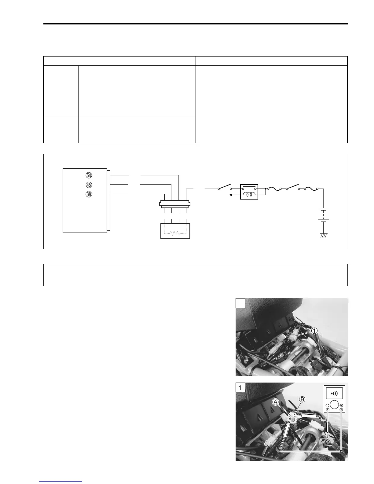
1) Turn the ignition switch OFF.
2) Remove the footboard. (#AN650K3 9-18)
3) Check the HO2 sensor coupler
1 for loose or poor contacts.
If OK, then check the HO2 sensor lead wire continuity.
4) Disconnect the HO2 sensor coupler.
5) Check the continuity between B/G wire
A and ground.
6) Also, check the continuity between B/G wire
A and B/Br wire
B. If the sound is not heard from the tester, the circuit condi-
tion is OK.
! 09900-25008: Multi-circuit tester set
& Tester knob indication: Continuity test (%)
DETECTED CONDITION POSSIBLE CAUSE
C44
(P0130)
HO2 sensor output voltage is not input
to ECM during engine operation and
running condition.
(Sensor voltage < 1.0 V)
In other than the above value, C44
(P0130) is indicated.
• HO2 sensor circuit open
C44
(P0135)
The heater can not operate so that
heater operation voltage is not supplied
to the oxygen heater circuit.
• HO2 sensor lead wire/coupler connection
• Battery voltage supply to the HO2 sensor.
ECM
Side-stand
relay
Ignition
switch
Engine stop
switch
O/W
Bl
B
B/Br
B/G
Y/W
HO2 sensor
OX
OXH
E2
To side-stand
switch
B
W
When using the multi-circuit tester, do not strongly touch the terminal of the ECM coupler with
a needle pointed tester probe to prevent the terminal damage or terminal bend.
SAMPLE
 Loading...


