AN650/AK7 (’07-MODEL) 27
“C49” (P1656) PAIR CONTROL SOLENOID VALVE CIRCUIT MALFUNCTION
INSPECTION
Step 1
1) Turn the ignition switch OFF.
2) Remove the lower leg shield. (#AN650K3 9-10)
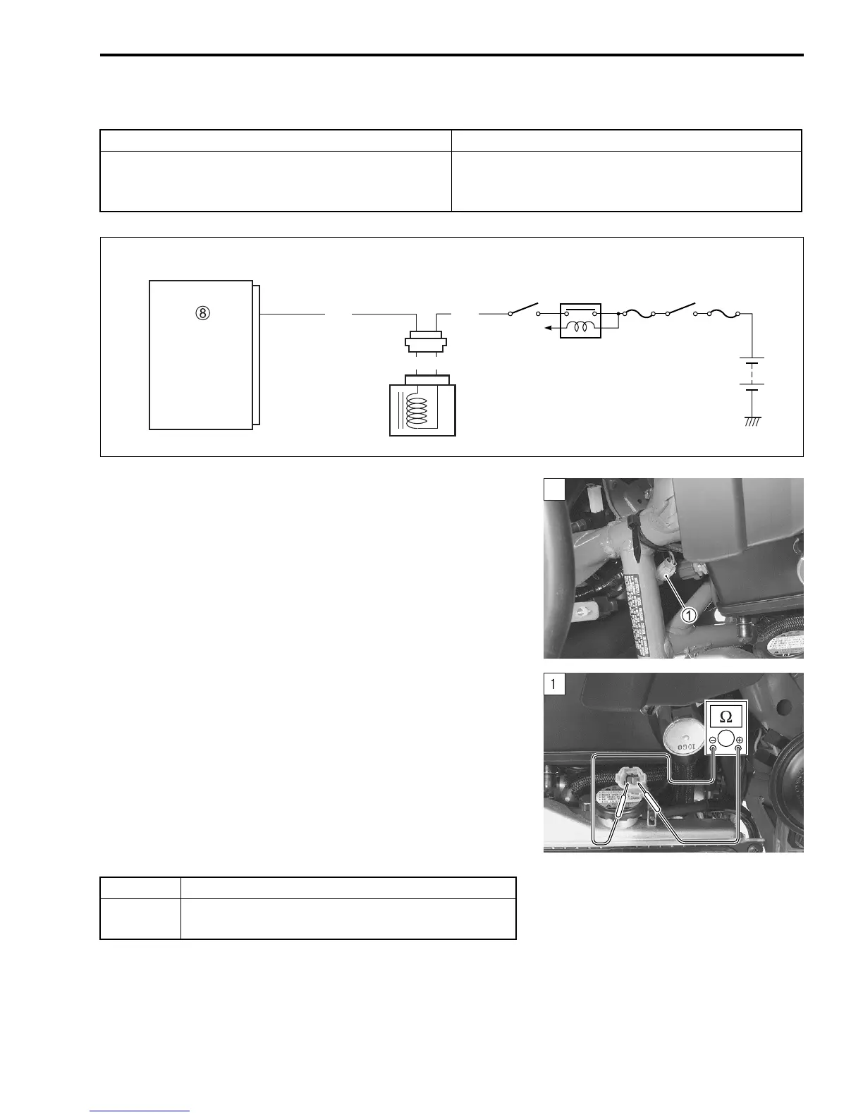
3) Check the PAIR control solenoid valve coupler
1 for loose or
poor contacts.
If OK, then measure the PAIR control solenoid valve resis-
tance.
4) Remove the PAIR control solenoid valve coupler.
5) Measure the resistance between terminals (valve side).
$ PAIR control solenoid valve resistance:
20 – 24 Ω at 20 °C (68 °F)
(Terminal – Terminal)
! 09900-25008: Multi-circuit tester set
) Tester knob indication: Resistance (Ω)
Is the resistance OK?
6) After repairing the trouble, clear the DTC using SDS tool.
(Refer to the SDS operation manual for further details.)
DETECTED CONDITION POSSIBLE CAUSE
PAIR control solenoid valve voltage is not input to
ECM.
• PAIR control solenoid valve circuit open or short
• PAIR control solenoid valve malfunction
• ECM malfunction
ECM
Side-stand
relay
Ignition
switch
Engine stop
switch
O/W
PAIR control
solenoid valve
G/Bl
PAI R
To side-stand
switch
RB
YES Go to Step 2.
NO
Replace the PAIR control solenoid valve with a
new one.
SAMPLE
 Loading...


