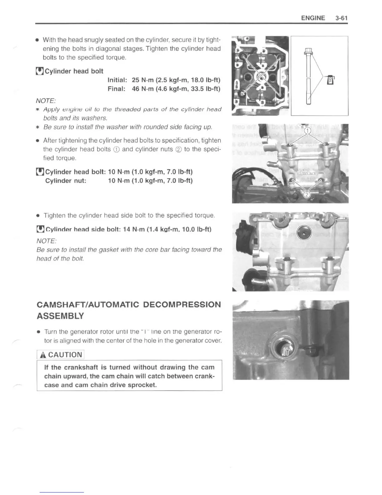
• With the head snugly seated on the cylinder, secure it by tight-
ening the boits
in
diagonal stages. Tighten the cylinder head
bolts to the specified torque.
r!)
Cylinder
head
bolt
NOTE:
Initial: 25 N·m (2.5 kgf-m, 18.0 Ib-ft)
Final:
46
N·m (4.6 kgf-m, 33.5 Ib-ft)
•
Apply
t!llyillt:
oil
10
Ihe
Ihreaded
parts
of
the
cylinder
helld
bolts
and
its washers.
* Be sure
to
install the washer with rounded side facing up.
• After tightening the cylinder head bolts
to
specification, tighten
the cylinder head bolts
CD
and cylinder nuts ® to the speci-
fied torque.
r!)
Cylinder
head
bolt
: 10 N·m
(1
.0 kgf-m, 7.0
Ib
-ft)
Cylinder
nut
: 10 N·m (1.0
kgf-m
, 7.0 Ib-ft)
• Tighten the cylinder head side bait
to
the specified torque.
~
Cylinrt
...
h .. ad
side
bolt:
14 N·m (1.4 kaf-m. 10.0 Ib-ftl
NOTE:
Be sure
to
install the gasket with the core
bar
facing toward the
head
of
the bolt.
CAMSHAFT/AUTOMATIC
DECOMPRESSION
ASSEMBLY
• Turn the generator rotor until the " 1
..
line on the generalOr ro-
tor
is
aligned with the center of the hole
in
the generator cover.
[ A
CAUTlg
Nl
If
the
crankshaft
is
turned
without
drawing
the
cam
chain
upward
,
the
cam chain
will
catch
between crank-
case
and
cam
chain
drive
sprocket.
ENGINE 3-
61
http://www.motorcycle.in.th
 Loading...


