10-20 SERVICING INFORMATION
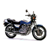
COOLING SYSTEM HOSE ROUTING
Frame
Wiring
harness
Reservoir tank
overflow hose
Clamp
Pass the drain hose
between the air cleaner,
upper crankcase
and frame bridge.
Frame
bridge
Fuel tank water
drain hose
The clamp end
should face
downward.
Yellow mark
The clamp end
should face upward.
6 N·m
(0.6 kgf-m, 4.5 lbf-ft)
Thermostat
The clamp screw
head should face
right side.
The clamp screw
head should face
forward.
White mark
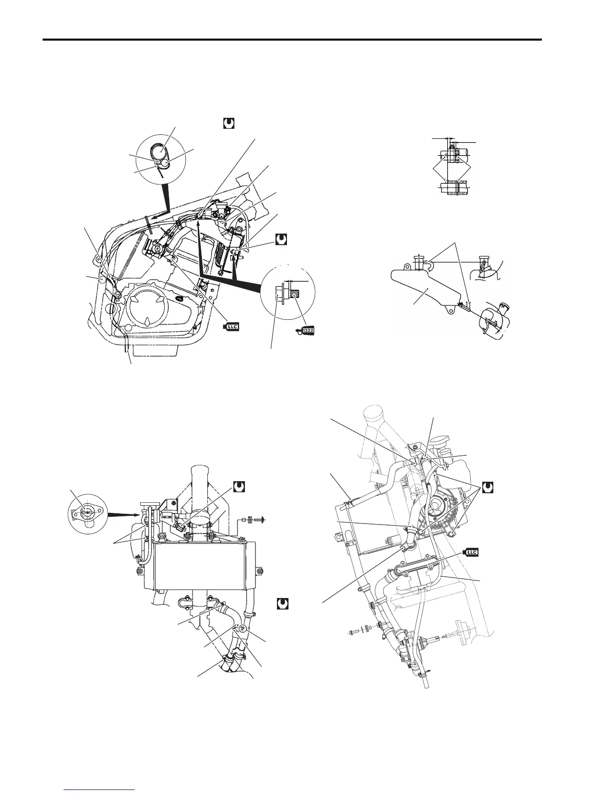
The clamp
screw head
should face
forward.
Do not contact
the clamp screw
and bracket.
The clamp screw head
should face right side.
The clamp
end should
face upward.
The clamp end
should face
downward.
White mark
The clamp screw
head should face
right side.
Yellow mark
10 N·m
(1.0 kgf-m, 7.0 lbf-ft)
Connect the reservoir tank
overflow hose and reservoir
tank inlet hose as shown.
40 – 50
0 – 10
UP
Reservoir tank
2 – 8 mm
(0.08 – 0.31 in)
Clearance
Stopper
Marking
1.5 mm
(0.06 in)
6 N·m
(0.6 kgf-m, 4.5 lbf-ft)
First, tighten the reservoir tank mounting bolt (upper),
and then, tighten the reservoir tank mounting bolt (lower).
18 N·m
(1.8 kgf-m, 13.0 lbf-ft)
7 N
.
m
0.7 kgf-m
5.0 lbf-ft
( )
Reservoir tank
overflow hose
MAX.

 Loading...