English
Done
Com
Scheduler
Archive
1/4
Full>Wait 2m for Restart
Execute
1/3
Execute
1/2
Readwrite
BSP load
a-snapshot sa.-> SD
Sett. service save
Sett. factory load
Sett. service load
Restart required !
Filter
+Settings load <- SD
Settings save-> SD
SD-Card
1/10Save / load
0.0 h
0
0.0 h
0
0.0 h
0.0 h
0
0.0 h
0
0.0 h
-Reversing valve
-Compressor 2
-Compressor 1
Circuit 2
-Reversing valve
-Compressor 2
-Compressor 1
Circuit 1
1/13Operation hours
Yes
No
1/2
No
Yes
18.0°C
7.0 K
10.0 K
-Circuit 2
-Circuit 1
Manual deice
Sour.t.defr.fin.
DT defrost shutdown
DT defrost
1/7Deice
Stage 2
Stage 1
Off
1/3
Manual
Automatic
1/2
Off
Automatic
Off
Automatic
Off
Automatic
0 %
Automatic
0 %
Automatic
0 %
Manual
Stage 1
Manual
0 %
Manual
Stage 1
Manual
Supply pump
-Circuit 2
-Circuit 1
Reversing valve
-Circuit 2
-Circuit 1
Exp. valve
-Circuit 2
-Circuit 1
Source Fan
1/22Outputs manual test
Reduced
Heating
Low load
None
1/4
NC
NO
1/2
Réduced
NC
Ecternal switch
On/Off input
1/2
Remote control configuration
30s
30.0°C
-----------
30s
off
-i Min. low. press.
Circuit 2
------------------------------
-i Min. low. press.
Circuit 1
1/5Refrig.circuit config
Active
Passive
1/2
Off
On
1/2
100.0%
20.0%
40.0%
80.0%
---------------
120s
72h
Active
---------------
Off
Capacity for max speed
Mod.pump standby speed
Mod.pump min speed
Mod.pump max speed
--------------------------
Anti-seizing duration
Anti-seizing frequency
Anti seizing act.
--------------------------
Continuous pump
1/10Pump configuration
17bar
14bar
10bar
18bar
10%
100%
-----------
17bar
14bar
10bar
18bar
10%
100%
-Heat.pressure setp.
-Cool.pressure setp.
-Mod.fan pressure de
-Mod.fan pressure se
-Mod.fan min speed
-Mod.fan max speed
Circuit 2
------------------------------
-Heat.pressure setp.
-Cool.pressure setp.
-Mod.fan pressure de
-Mod.fan pressure se
-Mod.fan min speed
-Mod.fan max speed
Circuit 1
1/11Fan configuration
20dKdT ret./sup. temp
Remote control
Circuit control
Supply pump
Source Fan
1/5Configuration
correct
Save / load
Operation hours
Deice
Outputs manual test
Configuration
Flow switch
1/6Service
Access
Services
Commissioning
Status
0
10
15
3
Speed
%
Mod. fan
max speed
Mod. fan
min speed
Mod.fan pressure de
PCd
bar
12 SysAqua
2.2. SERVICE MENU
Limited access with the "Maintenance" prole.
2.2.1. WATER FLOW
CONTROLLER
The water ow controller is used to
ensure the presence of sufcient
ow in the water system. A water
ow that is null or too low stops the
unit.
The controller can have two statuses:
² Correct
² Default
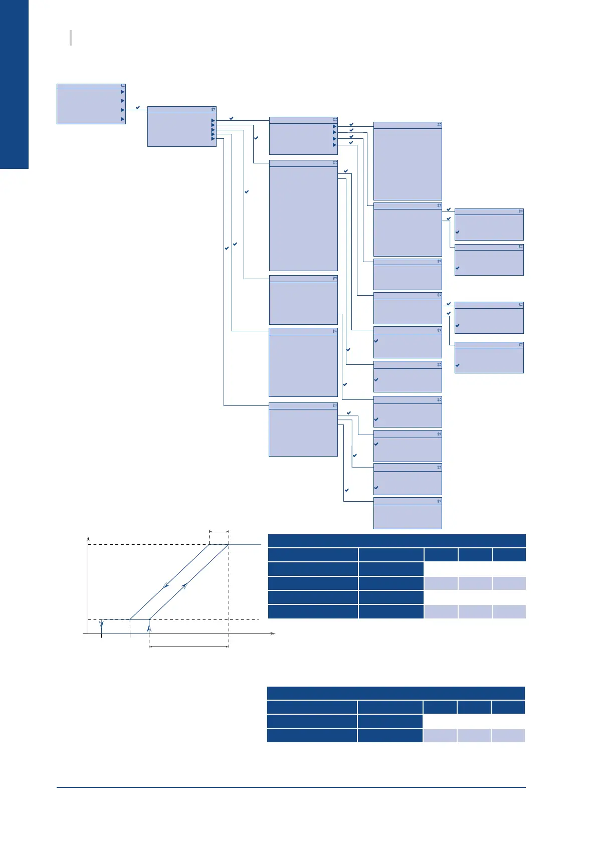
2.2.2. CONFIGURATION
The speed of modulating fans is controled with a ramp
depending on the condensing pressure in cooling mode with
a low speed stage. In heating mode, the speed is xed to the
value of the "Mod. fan max speed" setting.
Circuit 1 / 2
Parameter Code default min max
Mod. fan max speed MdlMaxSpd
100% 0% 100%
Mod. fan min speed MdlMinSpd
10% 0% 100%
Mod.fan pressure se MdlStartPCdn
18 bar 16 bar 20 bar
Mod.fan pressure de MdlDeltaPCdn
10 bar 8 bar 10 bar
2.2.2.1. FAN CONFIGURATION
2.2.2.1.1. MODULATING FANS
2.2.2.1.2. AC FANS
The AC fan speed is managed with a proportional control loop.
² function of the condensing pressure in
cooling mode
² function of the evaporation pressure in
heating mode
The high or low speed depends on this proportional controller.
If both circuits have the same capacity, the conguration of a circuit will be automatically copied on the
second circuit.
Circuit 1 / 2
Parameter Code default min max
Cool.pressure step. PC
16 bar 16 bar 20 bar
Heat.pressure step. PH
14 bar 12 bar 18 bar
 Loading...


