English
Information
The operating mode for a deicing cycle is described in in § DEICING, page 20.
Done
Com
Scheduler
Archive
1/4
Full>Wait 2m for Restart
Execute
1/3
Execute
1/2
Readwrite
BSP load
a-snapshot sa.-> SD
Sett. service save
Sett. factory load
Sett. service load
Restart required !
Filter
+Settings load <- SD
Settings save-> SD
SD-Card
1/10Save / load
0.0 h
0
0.0 h
0
0.0 h
0.0 h
0
0.0 h
0
0.0 h
-Reversing valve
-Compressor 2
-Compressor 1
Circuit 2
-Reversing valve
-Compressor 2
-Compressor 1
Circuit 1
1/13Operation hours
Yes
No
1/2
No
Yes
18.0°C
7.0 K
10.0 K
-Circuit 2
-Circuit 1
Manual deice
Sour.t.defr.fin.
DT defrost shutdown
DT defrost
1/7Deice
Stage 2
Stage 1
Off
1/3
Manual
Automatic
1/2
Off
Automatic
Off
Automatic
Off
Automatic
0 %
Automatic
0 %
Automatic
0 %
Manual
Stage 1
Manual
0 %
Manual
Stage 1
Manual
Supply pump
-Circuit 2
-Circuit 1
Reversing valve
-Circuit 2
-Circuit 1
Exp. valve
-Circuit 2
-Circuit 1
Source Fan
1/22Outputs manual test
Reduced
Heating
Low load
None
1/4
NC
NO
1/2
Réduced
NC
Ecternal switch
On/Off input
1/2
Remote control configuration
30s
30.0°C
-----------
30s
off
-i Min. low. press.
Circuit 2
------------------------------
-i Min. low. press.
Circuit 1
1/5Refrig.circuit config
Active
Passive
1/2
Off
On
1/2
100.0%
20.0%
40.0%
80.0%
---------------
120s
72h
Active
---------------
Off
Capacity for max speed
Mod.pump standby speed
Mod.pump min speed
Mod.pump max speed
--------------------------
Anti-seizing duration
Anti-seizing frequency
Anti seizing act.
--------------------------
Continuous pump
1/10Pump configuration
17bar
14bar
10bar
18bar
10%
100%
-----------
17bar
14bar
10bar
18bar
10%
100%
-Heat.pressure setp.
-Cool.pressure setp.
-Mod.fan pressure de
-Mod.fan pressure se
-Mod.fan min speed
-Mod.fan max speed
Circuit 2
------------------------------
-Heat.pressure setp.
-Cool.pressure setp.
-Mod.fan pressure de
-Mod.fan pressure se
-Mod.fan min speed
-Mod.fan max speed
Circuit 1
1/11Fan configuration
20dKdT ret./sup. temp
Remote control
Circuit control
Supply pump
Source Fan
1/5Configuration
correct
Save / load
Operation hours
Deice
Outputs manual test
Configuration
Flow switch
1/6Service
Access
Services
Commissioning
Status
1/4Main Menu
15SysAqua
This menu is used to congure the different control parameters for a deicing cycle:
² DT defrost: If the air temperature is less than the heat exchanger temperature at the difference
indicated, the circuit switches to deicing mode (range: [10-20K], default value 10K)
² DT defrost shutdown: If the air temperature is less than the heat exchanger temperature at the
difference indicated while the circuit is in shutdown phase, the circuit switches to deicing mode
(range: [10-20K], default value 7K).
² Sour.t.defr.n.: The deicing stops when this temperature is reached by the heat exchanger sensor.
(range: [12-20°C], default value 18°C).
This menu can also be used to manually force the deicing of a circuit. The unit must be operating for this to
be done.
Changing the value of the relevant circuit line
from No to Yes in the "Manual Deicing" heading
will start the manual deicing. This deicing will
stop
² If this value is set to No while the manual
deicing is in progress
² Or according to the usual conditions
for stopping the deicing (Refer to the §
DEICING, page 20)
If the deicing stops according to the usual conditions, set the manual deicing value from "Yes" to
"No".
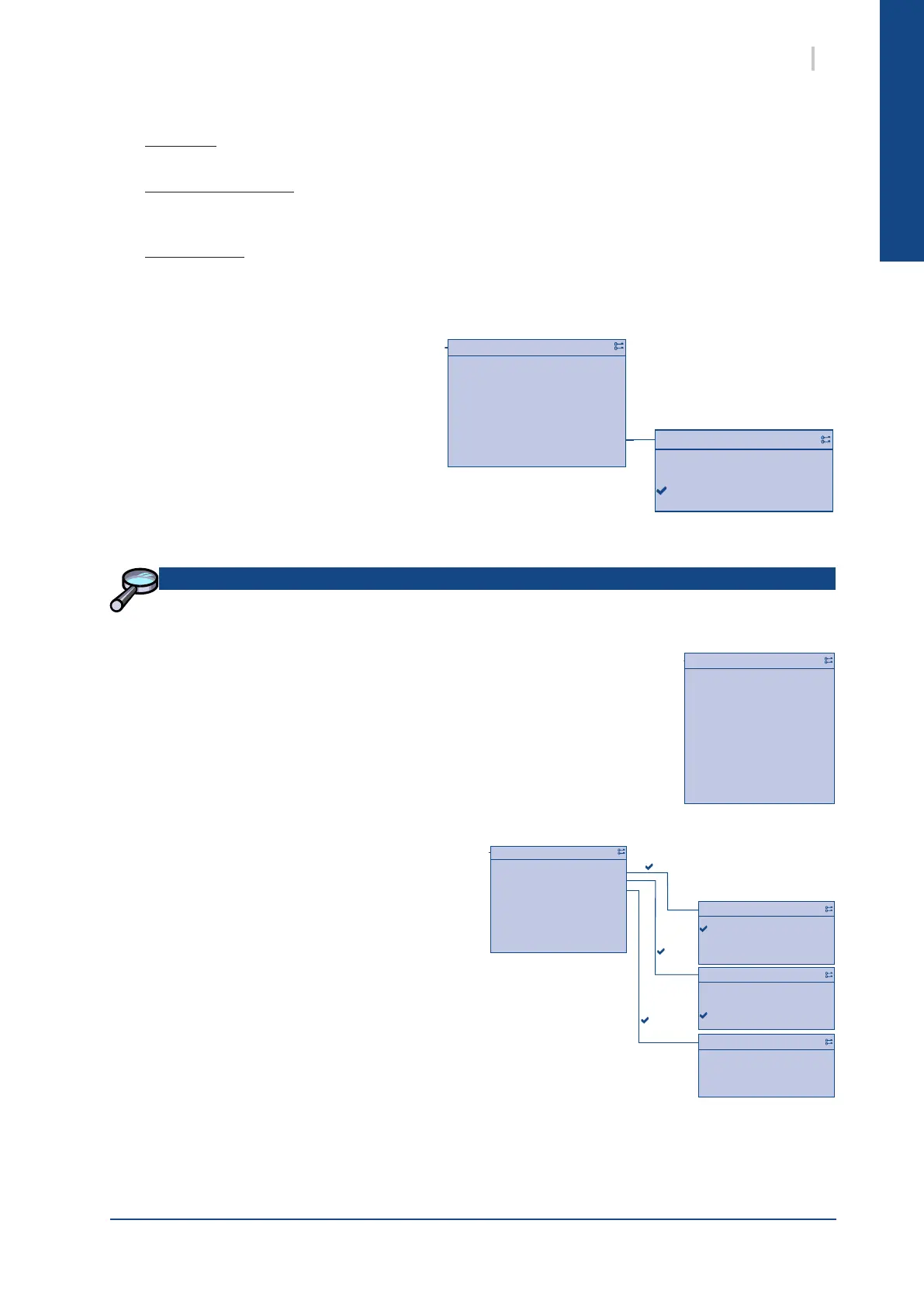
2.2.5. DEICING
2.2.4. OPERATION TIME
On this screen is used to view:
² for each compressor
the operation time
the number of cycles
² for each reversing valve
the operation time.
2.2.6. SAVE / LOAD
The Save/Load menu is used to manage the
parametering of the unit
² SD-Card indicates if an SD card is in the
controller and its state : read/write or read only
² Setting save-> SD: save the curent parameter
le on the SD-Card
² Setting load-> SD: Replace the current unit parametring with the
parameter l of the SD-Card
² Filter: Indicates the les which have not to be saved on the SD-card
² Sett.service load: Load the parameters which have been saved
previously with the Sett.factory save menu
² Sett.factory load: Load the parameters of the unit when delivered by the factory
² Sett.factory save: Save the current parameter of the unit on the controller
² BSP load: Updates the Bios
 Loading...


