7 – Other module parameter setting screens
4 Module name
o This shows the module name and user module name for
the selected bus. If the user module name has not been
defined, the module name will be shown as “MAIN L/R”, for
example.
o Tap the user module name area to open the MODULE
NAME Screen where the user module name and set
module color can be changed. (See “MODULE NAME
screen” on page 160.)
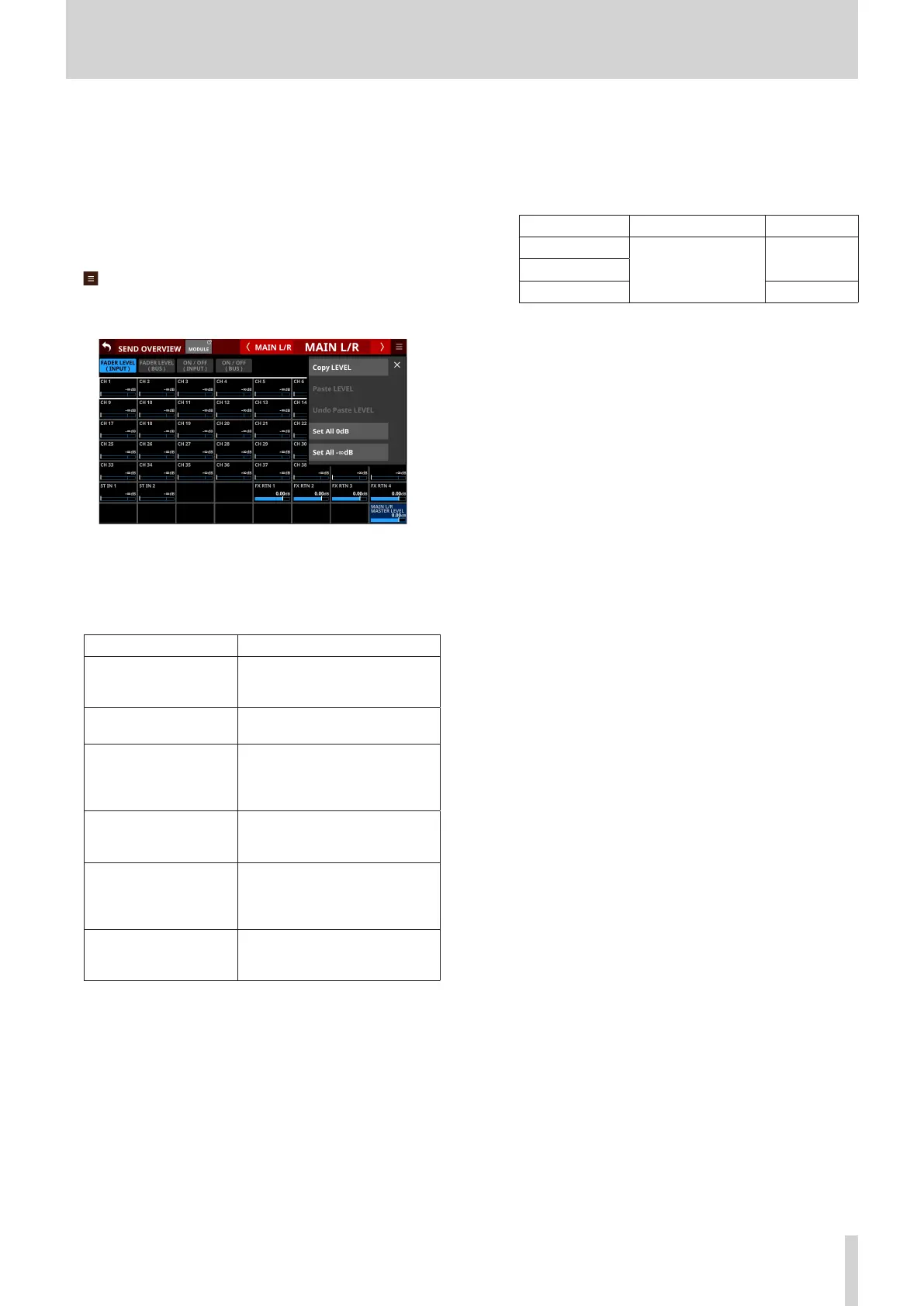
5 button
Tap this button to open the SEND OVERVIEW menu for the
MAIN L/R bus.
Tap menu items to change parameter settings for the MAIN
L/R bus. (See “SEND OVERVIEW menu” on page 156.)
6 Page selection buttons
Tap a page selection button to open that page.
The selected button will be highlighted.
Button Use
FADER LEVEL (INPUT)
This shows a list of FADER levels
for the CH 1–40, ST IN 1–2 and FX
RTN 1–4 modules.
FADER LEVEL (BUS)
This shows a list of FADER levels
for the MIX 1–22 modules.
ON / OFF (INPUT)
This shows a list of assignment
on/off states from the CH 1–40,
ST IN 1–2 and FX RTN 1–4
modules to the MAIN L/R bus.
ON / OFF (BUS)
This shows a list of assignment
on/off states from the MIX 1–22
modules to the MAIN L/R bus.
SEND PAN (INPUT)
This shows a list of pan/balance
settings from the CH 1–40, ST IN
1–2 and FX RTN 1–4 modules to
the MAIN L/R bus.
SEND PAN (BUS)
This shows a list of pan/balance
settings from the MIX 1–22
modules to the MAIN L/R bus.
7 FADER levels
o This shows a list of FADER level setting states for the CH
1–40, ST IN 1–2 and FX RTN 1–4 modules.
o When a selection frame is shown, use corresponding LCD
knobs (lit blue) to adjust FADER levels.
Module name Range default
CH 1–40
-∞ dB – +10 dB
-∞ dB
ST IN 1–2
FX RTN 1–4 0.0 dB
8 MAIN L/R MASTER LEVEL
This adjusts the FADER level of the MAIN L/R Master module.
Range: -∞ dB – +10 dB (default: 0.0 dB)
When the selection frame is shown, turn LCD knob 8 (lit blue)
to adjust it.
9 FADER levels
o This shows a list of FADER level setting states for the MIX
1–22 modules.
o When a selection frame is shown, use corresponding LCD
knobs (lit blue) to adjust FADER levels.
Range: -∞ dB – +10 dB (default: 0.0 dB)
0 MAIN L/R assignment state indicators/buttons for
input modules
o This shows a list of assignment on/off states from the CH
1–40, ST IN 1–2 and FX RTN 1–4 modules to the MAIN L/R
bus.
o Tap these buttons to turn on/off assignments to the MAIN
L/R bus.
Options: on (default), off
When this is on, the button will appear highlighted.
q MAIN L/R assignment state indicators/buttons for
BUS modules
o This shows a list of assignment on/off states from the MIX
1–22 modules to the MAIN L/R bus.
o Tap these buttons to turn on/off assignments to the MAIN
L/R bus.
Options: on, off (default)
When this is on, the button will appear highlighted.
w PAN/BAL for CH 1–40, ST IN 1–2 and FX RTN 1–4
modules
o This shows a list of setting states for pan/balance from the
CH 1–40, ST IN 1–2 and FX RTN 1–4 modules to the MAIN
L/R bus.
o When a selection frame is shown, use corresponding LCD
knobs (lit yellow) to adjust the pan/balance.
Range: L100 – C – R100 (default: C)
e MIX 1–22 module PAN/BAL
o This shows a list of setting states for pan/balance from the
MIX 1–22 modules to the MAIN L/R bus.
o When a selection frame is shown, use corresponding LCD
knobs (lit yellow) to adjust the pan/balance.
Range: L100 – C – R100 (default: C)
TASCAM Sonicview 16/Sonicview 24 V1.1.0 155
 Loading...