47
Installing the device
WARNING! Always pull the mains plug before opening the casing!
Only work on the inside of the control system when it is dead.
Loosen the screw on the top of the casing and remove the lid. The electronics for the con-
trol unit is in the lid. Contact pins provide a connection to the clamps in the lower part of the
casing when the lid is put on again. The body of the casing can be screwed to the wall (with
the cable ducts facing down) through the two holes using the fastening materials provided.
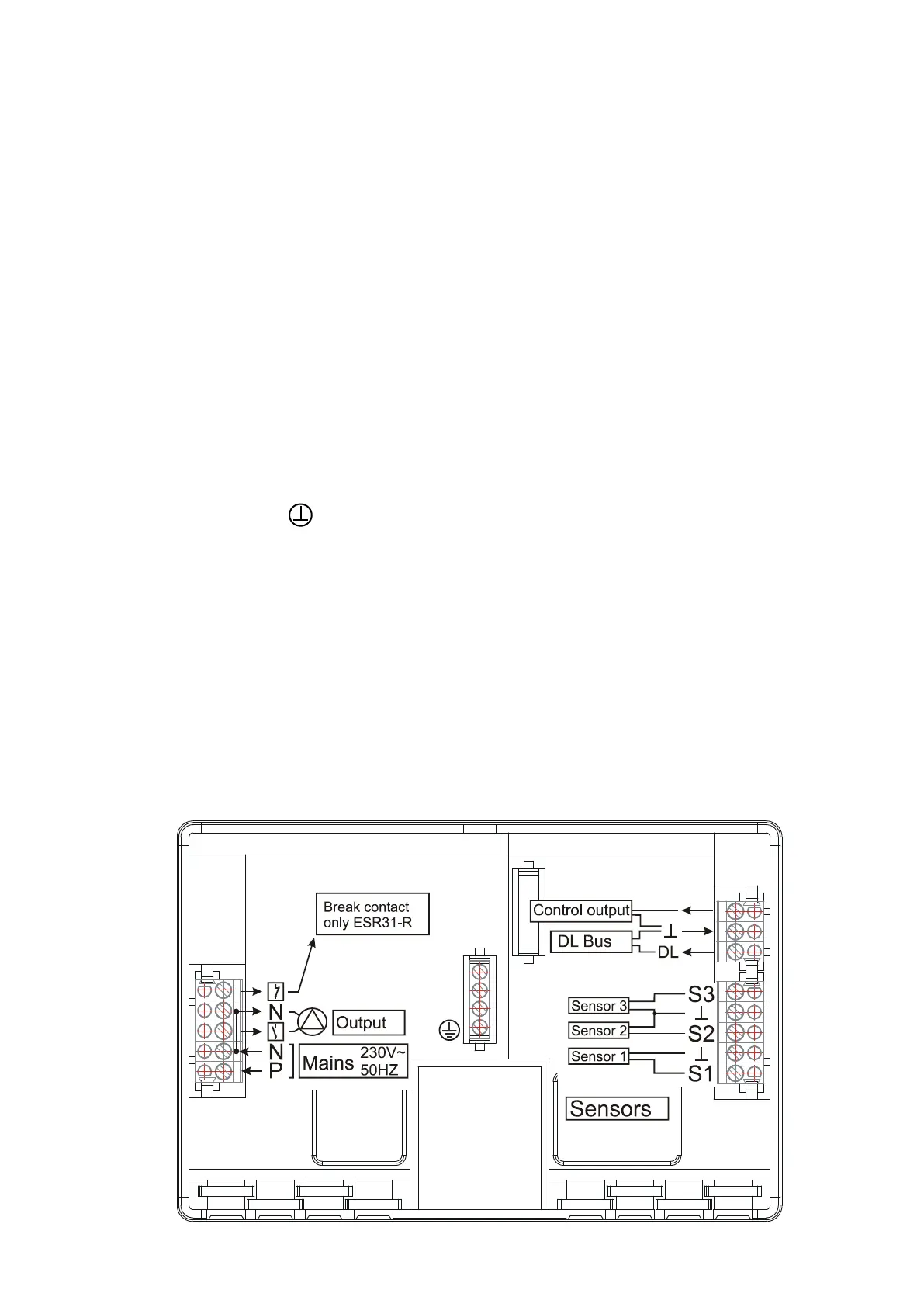
Electrical connection
Caution: Only a trained electrician may provide the electrical connection in compliance
with local guidelines. The sensor lines must not be laid in the same cable channel as the
supply voltage. The maximum output load amounts to (VD) 1.5A in the speed version and
(VR) 2.5A in the relay version. If filter pumps are directly connected, their rating plate must be
minded. The appropriate strip terminal must be used for all protective conductors.
Note: The system has to be grounded properly and furnished with surge arresters to pro-
tect it from damage due to lightening. Sensor failures due to storms and static electricity are
usually the result of faulty construction.
The sensor masses are internally connected and can be exchanged as needed.
Control output (0 – 10V / PWM)
This output is intended for the speed control of the latest generation electronic pumps
(PWM) or for controlling the burner performance (0 - 10V). It can be operated via respective
menu functions parallel to the output.
Data link (DL-Bus)
The bi-directional data link (DL-Bus) was developed for the ESR/UVR series and is only
compatible with products of the Technische Alternative company. Any cable with a cross
section of 0.75 mm² can be used for the data link (e.g. twin-strand) having a max. length of
30 m. For longer cables, we recommend the use of shielded cable.
Interface to PC: The data is cached via the data converter D-LOGG, Bootloader BL-NET
or C.M.I. interface and transferred to the PC on request. BL-NET and C.M.I. require a sepa-
rate 12V power unit for power supply.
 Loading...