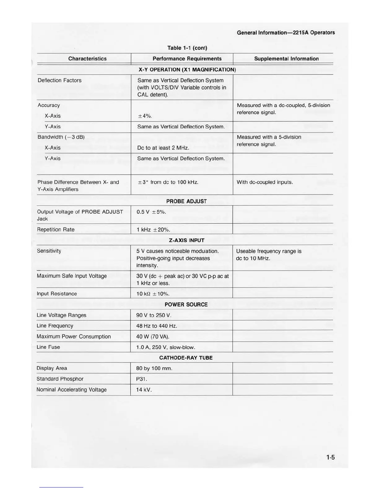
Characteristics
Deflection Factors
Accuracy
X-Axis
Y-Axis
Bandwidth (- 3 dB)
X-Axis
Y-Axis
Phase Difference Between
X-
and
Y -Axis Amplifiers
Output Voltage
of
PROBE ADJUST
Jack
Repetition Rate
Sensitivity
Maximum Safe Input Voltage
Input Resistance
Line Voltage Ranges
Line Frequency
Maximum Power Consumption
Li
ne Fuse
Display Area
Standard Phosphor
Nominal Accelerating Voltage
General lnformation- 221 SA Operators
Table 1-1 (cont)
Performance Requirements Supplemental Information
X-Y
OPERATION (X1 MAGNIFICATION)
Sarne as Vertical Deflection System
(with VOLTS/DIV Variable controls in
CAL
detent).
Measured with a de-coupled, 5-division
± 4%.
reference signal.
Same as Vertical Deflection System.
Measured with a 5-division
De
to
at
least 2 MHz.
reference signal.
Sarne as Vertical Deflection System.
± 3° from de
to
100 kHz. With de-coupled inputs.
PROBE ADJUST
0.5 V ± 5%.
1 kHz ± 20%.
Z-AXIS
INPUT
5 V causes noticeable modulation. Useable frequency range is
Positive-going input decreases de
to
10 MHz.
intensity.
30 V (de
+ peak ac)
or
30 VC p-p ac
at
1 kHz
or
less.
10
þÿk©
± 10%.
POWER SOURCE
90 V
to
250
V.
48 Hz
to
440 Hz.
40
W (70
VA).
1.0
A,
250
V, slow-blow.
CATHODE-RAY
TUBE
80 by 100 mm.
P31.
14 kV.
1
-5

 Loading...


