General l
nformation-2215A
Operators
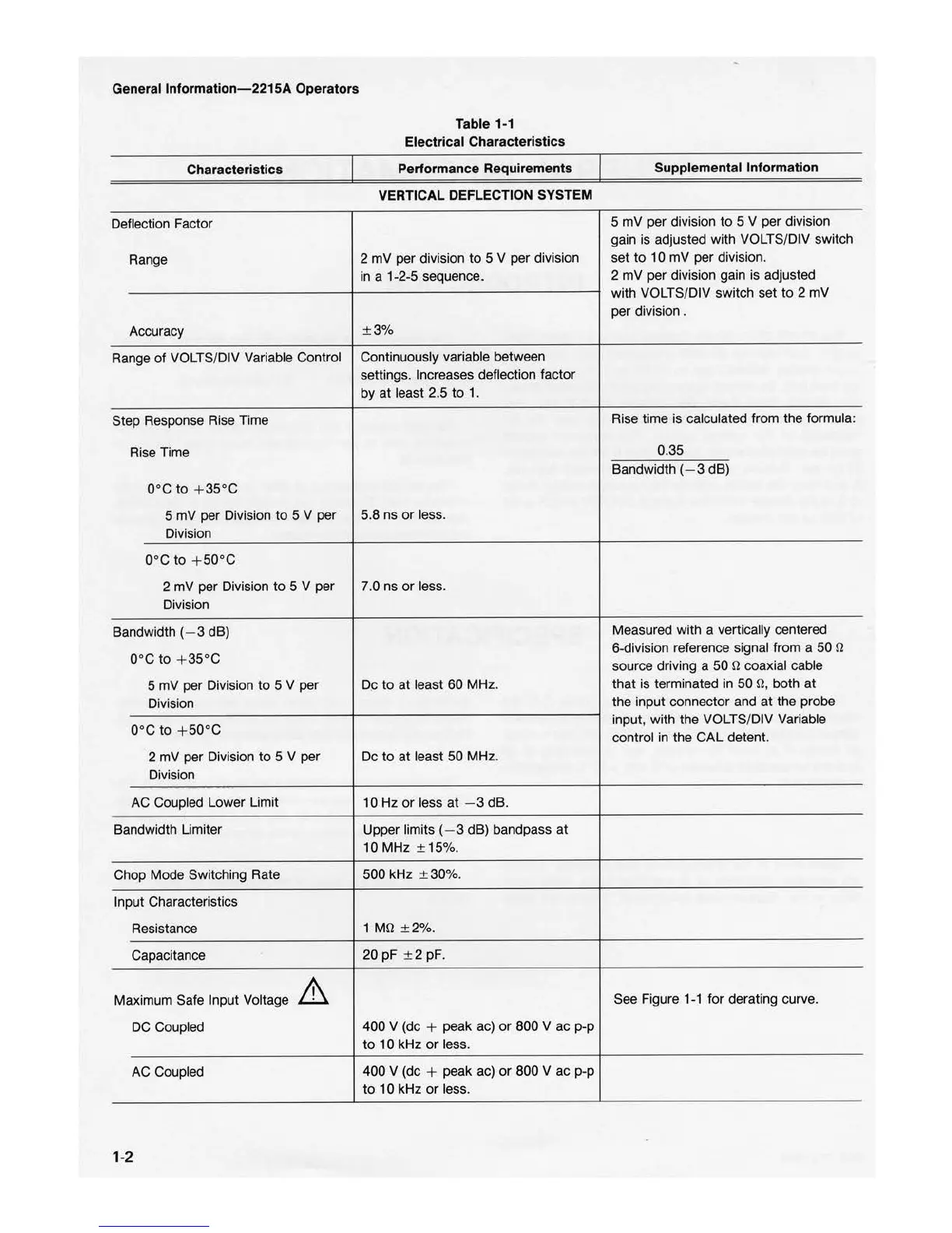
Characteristics
Deflection Factor
Range
Accuracy
Range of VOLTS/DIV Variable Control
Step Response Rise Time
Rise Time
0°c
to
+
35°c
5 mV per Division
to
5 V per
Division
0°c
to
+ 50°c
2 mV per Division
to
5 V per
Division
Bandwidth (- 3 dB)
0°c
to
+ 35°c
5 mV per Division to 5 V per
Division
0°c
to
+ 50°c
2 mV per Division
to
5 V per
Division
AC
Coupled Lower Limit
Bandwidth Limiter
Chop Mode Switching Rate
Input Characteristics
Resistance
Capacitance
Maximum Safe Input Voltage
DC
Coupled
AC Coupled
1-2
Table 1-1
Electrical Characte
ri
stics
Performance Requirements
VE
RTICAL DEFLE
CT
ION SYSTEM
2 mV per division
to
5 V per division
in
a 1-2-5 sequence.
±
3%
Continuously variable between
settings. Increases deflection factor
by at least 2.5
to
1.
5.8 ns
or
less.
7.0 ns
or
less.
De
to
at least
60
MHz
.
De
to
at least 50 MHz.
10 Hz
or
less
at
- 3 dB.
Upper limits (- 3 dB) bandpass at
10 MHz ± 15%.
500 kHz ± 30%.
1
þÿM©
± 2%.
20 pF ± 2 pF.
400 V (de + peak ac)
or
800 V ac p-p
to
10 kHz
or
less.
400 V
(de
+ peak ac)
or
800 V ac p-p
to
10 kHz
or
less.
Supplemental
In
formation
5 mV per division
to
5 V per division
gain is adjusted with VOLTS/DIV switch
set
to
10 mV per division.
2 mV per division gain is adjusted
with VOLTS/DIV switch set
to
2 mV
per division .
Rise time is calculated from the formula:
0.35
Bandwidth (- 3 dB)
Measured with a vertically centered
6-division reference signal from a 50
þÿ©
source driving a 50
þÿ©
coaxial cable
that is terminated in
50
þÿ©,
both
at
the input connector and
at
the probe
input, with the VOLTS/DIV Variable
control in the CAL detent.
See Figure
1-1
for derating curve.